
Install Instructions

(25mm)
1"
6"
(152mm)
12"
(152mm)
2
3
4
5
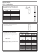
INSTALLATION –
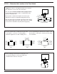
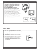
STEP 1 - Paddle Sizing
4
2
3
4
5
a. Trim paddle by cutting at appropriate notch
with non-serrated tin snips.
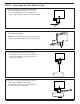
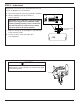
b. The paddle length can be adjusted if the
desired setpoint exceeds the maximum
adjustment as shown in flow rate chart. Use
the following formula to change the paddle
length.
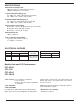
Pipe size determines the paddle length. Use the
chart below to choose the correct paddle size for
your installation.
Pipe size Paddle To Use
in. (mm)
1-1/4” (32) 1” Paddle
1-1/2” (40) 1” Paddle
2” (50) 6” Paddle Trimmed to 2
2-1/5” (65) 6” Paddle Trimmed to 2
3” (80) 6” Paddle Trimmed to 3
4” (100) 6” Paddle Trimmed to 4
6” (150) 6” Paddle
8” (200) to 16” (405) 6” Paddle
20” (500) to 36” (910) 12” Paddle
Note: 12” paddle will only fit on ‘L’ model units
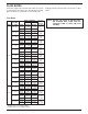
Pipe Flow No-Flow
Size NPT Maximum Maximum
in. (mm) Adjustment Adjustment
2 (50) 34.63 30.43
2
1
/2 (65) 54.00 47.46
3 (80) 92.94 81.69
3
1
/2 (90) 133.67 117.49
4 (100) 183.35 161.15
5 (125) 322.61 283.55
6 (150) 510.70 448.87
7 (180) 705.05 619.67
8 (200) 1014.47 891.62
9 (230) 1302.47 1144.79
10 (250) 1791.70 1574.74
12 (300) 2776.04 2439.88
14 (350) 3729.02 3255.02
16 (400) 4869.81 4250.81
18 (450) 6164.08 5380.57
20 (500) 7661.11 6687.31
30 (750) 18202.0 15888.0
Series FS7-4 “K” Factor
Paddle Length =
K
_______________
Flow Rate (GPM)
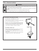
NOTE: If trimming the paddle for a no-flow action make sure
there is enough flow to activate switch.