
Install Instructions
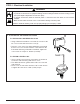

1" MAX
(25mm)
Paddle Arm
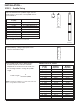
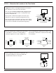
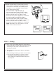
STEP 2 - Determine the Location of the Flow Switch
5
Fluid Flow
D
1 1/4" PIPE
CONNECTION
5 x D
MINIMUM
5 x D
MINIMUM
D= PIPE DIAMETER
• The flow switch
must be located in a horizontal section
of pipe
where there is a straight horizontal run of at least 5
pipe diameters on each side of the flow switch.
• The flow switch
must be installed in the upright position
as shown with arrow mark on side of casting in the same
direction as fluid will flow.
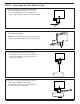
• Some system conditions that require more than 5 pipe
diameters are high viscosity fluid and high fluid velocity.
• The flow switch must be installed in the pump suction piping
when spring-loaded check valves and/or other close coupled
accessories are installed in the pump discharge piping.
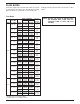
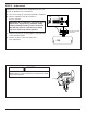
a. The flow switch must be installed in the pipe using
a threaded tee connection or welding fitting of
minimum length such as a half coupling. Use a
face or hex bushing to reduce the tee outlet to 1 1/4”
pipe thread if a reduced tee outlet thread size fitting
is not available.
b. When installing brazed/soldered copper pipe, size
the threaded adapter to ensure the paddle arm
extends into the main run of the pipe
2"
(50mm)
1
1
/4"
(32mm)
1
1
/2"
(40mm)
1
1
/4"
(32mm)
2"
(50mm)
1
1
/2"
(40mm)
1
1
/4" (32mm)
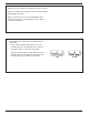
FACE OR HEX.
BUSHING
2" (50mm)
3" (80mm)
2" (50mm)
3" (80mm)
1
1
/4" (32mm) 1
1
/4" (32mm)
1
1
/2" (40mm) 1
1
/2" (40mm)
2
1
/2" (65mm) 2
1
/2" (65mm)
Threaded
Pipe
Threaded
Pipe
Welded
Pipe
2" (50mm)
3" (80mm)
1" MAX
(25mm)
4" (100mm)
6" (150mm)
2" (50mm)
3" (80mm)
4" (100mm)
6" (150mm)
2
1
/2" (65mm) 2
1
/2" (65mm)
1
1
/4" (32mm)