
Install Instructions
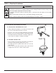
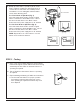

a. Place cover on flow switch and turn on power. Initiate
fluid flow through the system. Observe the device being
activated by the flow switch to determine if device is
operating as required.
b. Turn off fluid flow to determine if device is operating
as required.
c. Repeat initiating and turning off fluid flow several times
to test flow switch and device for proper operation.
- If operating as required, put system into service.
- If not operating as required, flow switch may need
to be adjusted.
OFF
ON
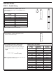
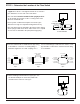
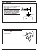
d. Based upon the mode of operation (“Flow” or “No-
Flow”) required, complete the appropriate steps to
connect wires to flow switch. Use a Phillip’s head
screwdriver to loosen and tighten switch terminal
screws when attaching wires.
For “Flow” Mode of Operation (Fig. 1)
If the flow switch will be used to actuate a signal,
alarm or other device when
flow
occurs, connect
the wire from that device to the “N.O.” contact.
Connect the “Hot” power supply wire to “C” terminal.
For “No Flow” Mode of Operation (Fig. 2)
If the flow switch will be used to actuate a signal,
alarm or other device when
no flow
occurs, connect
the wire from that device to the “N.C.” contact.
Connect the “Hot” power supply wire to “C” terminal.
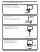
NOTE: Repeat above to connect wires to second
switch on “D” model flow switches.
STEP 5 - Testing
9
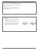
Flow
Opens
Circuit
Normally
closed
3
Common
1
Flow
Closes
Circuit
2
(
(
Normally
open
(
(
Common
(
(
FS4-3
LINE
LOAD
Fig. 1
HOT
31
2
FS4-3
LINE
LOAD
Fig. 2
HOT
31
2
FS7-4 Illustrated