
Install Instructions


3
a. The line on the casting of the model 64 must be installed above the lowest permissible water level
determined by the boiler manufacturer.
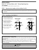
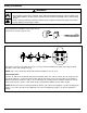
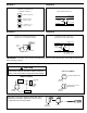
a. Study the figures to the right and determine which
figure shows how the 64 control will be attached to
the boiler.
Figure 1. Connect the upper equalizing pipe to
the riser going to the radiation or to the compression
tank. Connect the lower equalizing pipe to any
available opening in the side of the boiler. NOTE: If
no opening is available in the side of the boiler,
connect the lower equalizing pipe into the drain
connection.
Figure 2. If there is a tapping available on the
top of the boiler connect the upper equalizing pipe to
it. NOTE: During initial filling or after blow down the
upper equalizing pipe and possibly the 64 control will
have an air pocket. Connect a vent or bleed valve on
the top of the vertical equalizing pipe. If the Test-N-
Check (TC-4) valve is used the vacuum breaker can
be used to bleed the air pocket.
CAUTION: When bleeding an air pocket manually,
protect yourself from being burned with hot water.
Figure 3. If there is no tapping available on the
boiler, connect both the upper and lower equalizing
pipe into the vertical riser going to the radiation or to
the
compression tank. IMPORTANT: The horizontal
equalizing
pipe should not be above the horizontal
run going to the radiation. If it is, an air pocket will be
created and a vent or bleed will have to be installed.
STEP 2 - Installation of the Model 64
Model 64 – For Hot Water Boilers with 1” (25mm) Equalizing Lines
INSTALLATION –
TOOLS NEEDED:
One (1) flathead screwdriver and two (2) pipe wrenches.
For float type controls it is recommended that Test-N-Check
®
(TC-4) valves be used in the upper and
lower equalizing lines. They offer a functional means for testing the 64 control, and conform to the
ASME CSD-1 code.
STEP 1 - Determine the Location of the Low Water Cut-Off
VERTICAL RISER
TO RADIATION
HOT WATER
BOILER
MODEL
64
VERTICAL RISER TO RADIATION
OR COMPRESSION TANK
HOT WATER
BOILER
TC-4
TC-4
MODEL
64
HOT WATER
BOILER
AVAILABLE OPENING
IN TOP BOILER
AIR
VENT
MODEL
64
Figure 1
Figure 2
Figure 3
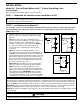
Test the Model 64 Before Leaving the Site
While the burner is operating open the blow-down valve, causing the water level to drop in the float chamber. As
the float drops the alarm circuit (if used) closes first; then on further drop the cut-off circuit will open, shutting the
burner off. NOTE: If no Test-N-Checks (TC-4) valves were used, do this test before filling the system completely.
IMPORTANT: Instruct boiler attendant to blow down the float chamber at least once a week during the heating
season, if operating pressure is below 15 psi (1 kg/cm
2
). If above 15 psi blow down once a day.
NOTE: On a new boiler installation, leaky system, or where the quality of the water is poor, blow down the control
more frequently.
Protect yourself when blowing down controls, hot water will flow out of the drain pipe attached to the blow-down valve.
Failure to follow this caution may result in serious burns.
!
CAUTION