
Install Instructions


6
TOP LEFT BOTTOM RIGHT
TOP12
34
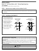
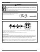
Electrical connector is movable into any one of four positions illustrated, by simply removing two black
headed screws and rotating housing.
NOTE: This control should be wired with materials suitable for use at 75˚C.
Switch Operation
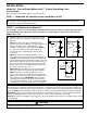
The No. 11 switch can be identified by a black terminal panel. The switch contains two (2) single pole sin-
gle throw switches to control the water feeder and the low water cut-off. The low water cut-off switch is
between terminals marked “1” and “2”. A second switch is located between terminals marked “3” and “4”.
This can be used to operate a low water alarm or a McDonnell & Miller electric water feeder.
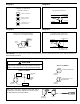
NOTE: Connect hot wire to terminal marked (2) ahead of all controls. See diagram 1 on the following page
(page 7) for control operation. See diagrams 2-4 on the following page (page 7) for proper application
wiring.
Wiring Instructions
• To prevent electrical shock, turn off the electrical power before making electrical connections.
• This low water cut-off must be installed in series with all other limit and operating controls installed on the
boiler. After installation, check for proper operation of all of the limit and operating controls, before leaving
the site.
Failure to follow this warning could cause electrical shock, an explosion and/or a fire, which could result in
property damage, personal injury or death.
!
WARNING
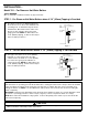
Cover
Using a flathead screwdriver, remove the one (1)
screw that secures the switch cover.