INSTRUCTION MANUAL MM-201J 246752 Series 67 and 767 Low Water Cut-Offs For Steam Boilers
OPERATION Maximum Steam Pressure: 20 psi (1.4 kg/cm2) Electrical Ratings Voltage Pump Circuit Rating (Amperes) Full Load Locked Rotor 120 VAC 7.4 44.4 240 VAC 3.7 22.2 Pilot Duty 125 VA at 120 or 240 VAC Note: 11 MV is rated at 24 VA @ 24 VAC to 120 VAC The Series 67 and Series 767 low water cut-offs are float-type boiler controls designed to interrupt current to the burner whenever the water drops to the cut-off level. a 2-1/2" (63.
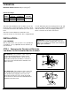
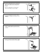
STEP 2 - Preparation a. Turn the boiler off. ON OFF b. Drain the water in the boiler to a level which is below the lower gauge glass tapping (B) of the control body (A). Allow the boiler to cool to 80˚F (27˚C) and allow the pressure to release to 0 psi (0 bar). ! A B CAUTION When using the tape sealant on the external threads of pipes or fittings, follow the manufacturers instructions. Use sparingly and do not place on the first thread. STEP 3 - Installing the New Low Water Cut-Off a.
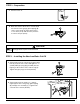
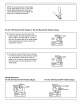
c. Using an adjustable wrench, install a a" (9.5mm) NPT compression fitting base (K) to the upper tapping (L) in the control (A). Tighten to 31 ft•lb (42 N•m). K L A d. Using a pipe wrench, install a 2" (13mm) nipple (M) into the upper tapping (N). Tighten to 31 ft•lb (42 N•m). e. Using a pipe wrench, install the pipe tee (P) (provided) onto the nipple (M) in the upper tapping (N). Tighten to 31 ft•lb (42 N•m). f.
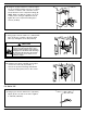
g. Position the tubing (Q) next to the compression fitting (K) and, using a pencil, mark the tubing (Q) for proper insertion into the compression fitting (K). Q K Remove the tubing (Q), and, using the tube cutter, cut the tubing to its proper length. h. Insert the tubing (Q) into the upper compression fitting (U) and tighten the fitting to 31 ft•lb (42 N•m). Q U i. Using two (2) pipe wrenches, rotate the upper tee (P) counterclockwise and the lower tee (J) clockwise. P J j.
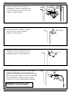
k. Using two (2) pipe wrenches, rotate the upper tee (P) clockwise and the lower tee (J) counterclockwise so that the end of the tube can be inserted into the lower compression fitting (K). NOTE: Make sure that the control is in a horizontal position. Using an adjustable wrench, tighten the lower compression fitting (K) to 31 ft•lb (42 N•m). P K J l. Using a pipe wrench, install a w" (19mm) NPT pipe (T) into the opening of the blow down valve (U) and tighten to 47 ft•lb (64 N•m).
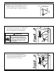
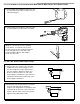
b. Install the control (A) by rotating it onto the 22" (63.5mm) nipple (X, as shown in Step a on previous page). Tighten to 109 ft•lb (148 N•m). A c. Using a pipe wrench, install a w" (19mm) NPT pipe (T) into the opening of the blow down valve (U) and tighten to 47 ft•lb (64 N•m). ! CAUTION To prevent burning or scalding, pipe blow-off discharge from blow-down valve to floor – allowing enough height for a pail under discharge pipe to collect blow down discharge.
STEP 4 - Electrical Wiring Directory: 67 Low Water Cut-Off and Uni-Match Water Feeder page 8 - 9 67 Low Water Cut-Off and 101 Water Feeder page 10 - 11 For 67 Low Water Cut-Off Installed with McDonnell & Miller Uni-Match Water-Feeder ! WARNING • To prevent electrical shock, turn off the electrical power before making electrical connections. • This low water cut-off must be installed in series with all other limit and operating controls installed on the boiler.
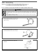
For 67 Low Water Cut-Off Installed with McDonnell & Miller Series 101-A Water-Feeder Y a. Using a flathead screwdriver, remove the one (1) screw that secures the low water cut-offs switch housing (Y). b. Using a flathead screwdriver, remove the two (2) screws that secure the feeder cover (BB). BB NOTE: To connect wires to the terminals on the burner, or low water cut-off, place the bare end of the wire under the terminal screw and tighten the screw with a flathead screwdriver.
COMMERCIAL WARRANTY Warranty.