
Install Instructions


11
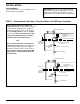
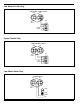
STEP 6 - Testing
a. Turn on power to boiler and pump circuits.
With the boiler empty, the pump should turn on (5
or 5-M switch models) or the valve open (7B or
7B-M switch models). The burner should remain off
and boiler should begin to fill with water.
b. For Automatic Reset Models
When water level in the gauge glass is approximately
1 3/8” (35mm) above the horizontal cast line, the
burner should turn on.
For Manual Reset Models
When water level in the gauge glass is approximately
1 3/8” (35mm) above the horizontal cast line, press
the manual reset button and the burner should turn on.
c. For 5 or 5-M Switch Models
When water level in the gauge glass is approximately
2 3/16” (56mm) above the horizontal cast line, the
pump should turn off.
For 7B or 7B-M Switch Models
When water level in the gauge glass is approximately
2 3/16” (56mm) above the horizontal cast line, the
valve should be closed.
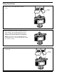
d. With the water in the boiler at its normal level and
burner on, SLOWLY open the blow-down valve
until it is fully open. As the water level in the gauge
glass begins to drop, verify that the following occurs.
For 5 or 5-M Switch Models
When water level drops to approximately 1 1/8”
(29mm) above the horizontal cast line, the pump
should turn on. When water level drops to the hori
zontal cast line, the burner should turn off.
For 7B or 7B-M Switch Models
As the water level drops, the valve should begin to
open. When the water level drops to approximately
1 1/8” (29mm) above the horizontal cast line, the
valve should be full open.
When the water level drops to the horizontal cast
line, the burner should turn off.
e. Close the blow-down valve after burner turns off
and restore water level to normal operating level.
f. Repeat testing procedure several times to ensure
proper operation of control.
g. After testing and verification of control operation,
the boiler can be returned to service.
– Dimensions shown are typical.
– The following testing procedure is only meant to serve
as a verification of proper operating sequence.
CAUTION
Immediately turn off all power if the burner turns on
with no water in the gauge glass. Investigate further
before continuing procedure.
!
CAUTION
If pump does not turn off or valve close, turn off
water supply to boiler. Investigate further before
continuing procedure.
!
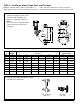
TROUBLESHOOTING
Erratic operation of the control is the most common symptom
that occurs. Erratic operation can be defined as pump and/or
burner switches not switching at proper levels. Refer to the
following list of items to check if the control is not operating
properly.
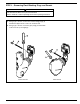
1. Float Ball is Crushed
Crushed floats are typically caused by improper blow-
down. Drain piping from blow-down valve to drain should
be checked for proper pitch and the blow-down procedure
followed when blowing down the control. Purchase and
install a new float ball after investigating and correcting
the problem.
2. Float Ball is Filled with Water
The seam weld on the float can sometimes deteriorate.
This can be caused by the type of chemical treatment
used in the boiler. While this is a rare occurrence, the
chemical treatment supplier should be consulted to deter-
mine if a reaction could occur. Purchase and install a new
float ball after investigating and correcting the problem.
3. Float Arm Springs are Bent
The pivot springs located on either side of the float rod
should be flat and straight. If they become bent, the usual
cause is mishandling of the unit during installation or
improper blow-down. The control should never be picked
up by the float ball or allowed to hang from the bowl by the
float. Drain piping from blow-down valve to drain should be
checked for proper pitch and the blow-down procedure
followed when blowing down control. Purchase and install
new control or head mechanism after investigating and
correcting the problem.
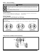
4. Switch Contact Springs Broken
The contact springs can break if the electrical rating is
exceeded. Purchase and install new switch assembly or
head mechanism after investigating and correcting the
problem.
5. Switch Contact Springs Misaligned
Misalignment of the contact arms is usually associated
with damage to the control during shipment or installation.
Purchase and install new switch assembly or head
mechanism after investigating and correcting the problem.
6. Internal (Wetted) Parts Dirty
The internal parts can operate improperly if dirt, scale or
rust is allowed to build. This condition can be a result of
not blowing down the control as recommended and/or
improper boiler water chemical treatment. Purchase and
install new control or head mechanism after investigating
and correcting the problem.