
Install Instructions


6
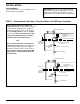
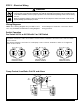
STEP 4 - Installing a Water Gauge Glass and Tri-Cocks
Tri-Cock Gauge Glass Tapping Gauge Glass Tapping
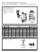
Tapping Pipe Size Center Distance
Unit B C D E F H J K L
193
1
⁄2 (15)
1
⁄2 (15)
1
⁄2 (15)
1
⁄2 (15)
1
⁄2 (15) 12
3
⁄4 (324)
193-A
1
⁄2 (15)
1
⁄2 (15)
1
⁄2 (15)
1
⁄2 (15)
1
⁄2 (15) 11
1
⁄2 (292)
193-B
3
⁄4 (20)
3
⁄4 (20)
3
⁄4 (20)
3
⁄4 (20)
3
⁄4 (20) 12
3
⁄4 (324)
193-D
1
⁄2 (15)
1
⁄2 (15)
1
⁄2 (15) 11
1
⁄2 (292)
193-G
1
⁄2 (15)
1
⁄2 (15)
1
⁄2 (15) 11
1
⁄2 (292)
194
1
⁄2 (15)
1
⁄2 (15)
1
⁄2 (15)
1
⁄2 (15)
1
⁄2 (15) 11
5
⁄8 (295)
194-A
1
⁄2 (15)
1
⁄2 (15)
1
⁄2 (15)
1
⁄2 (15)
1
⁄2 (15) 12
7
⁄8 (327)
194-B
3
⁄4 (20)
3
⁄4 (20)
3
⁄4 (20)
3
⁄4 (20)
3
⁄4 (20) 12
7
⁄8 (327)
CUT-OFF LEVEL
CUT-OFF
LEVEL
3"
3"
B
D
F
E
C
K
L
JH
a. Determine pipe size of tri-cock and
sight glass tappings for the control
being installed including center
distance of sight glass tappings.
NOTE:
These items are not provided with
control and must be purchased
separately
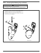
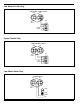
b. Install tri-cocks and gauge glass following
manufacturer’s instructions.
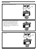
NOTE: A separate water column for installation of
gauge glass and tri-cocks may be required for boilers
with a Series 93 or Series 94 control. Follow the
manufacturer’s instructions to install the water column.
GAUGE GLASS
(TYPICAL)
TRI-COCK
(TYPICAL)