
Install Instructions


7
STEP 5 - Electrical Wiring
• To prevent electrical shock, turn off the electrical power before making electrical connections.
• This low water cut-off must be installed in series with all other limit and operating controls installed on the
boiler. After installation, check for proper operation of all of the limit and operating controls, before leaving
the site.
Failure to follow this warning could cause electrical shock, an explosion and/or a fire, which could result in
property damage, personal injury or death.
!
WARNING
2 4
1 3
BLUE
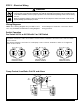
BOILER FEED PUMP OFF–
BURNER ON–ALARM OFF
BOILER FEED PUMP ON–
BURNER ON–ALARM OFF
BOILER FEED PUMP ON–
BURNER OFF–ALARM ON
RED
3 1
4 2
2 4
1 3
BLUE RED
3 1
4 2
2 4
1 3
BLUE RED
3 1
4 2
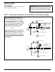
Switch Operation
For Series 93/193 or 94/194 with 5 or 5-M Switch
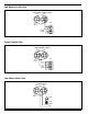
Wiring Diagrams
NOTE: The following diagrams are provided for refer-
ence only.
If available, manufacturer’s wiring diagrams
should always be followed to connect the device
being operated.
Red switch terminals 1 and 2 are for burner circuit contacts, terminals 3 and 4 are for the low level alarm
circuit contacts.
Blue switch terminals 3 and 4 are for feeder/pump control contacts, terminals 1 and 2 are for high level
alarm circuit contacts.
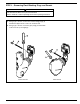
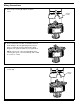
BLUE
NO. 5
SWITCH
TO BURNERTO PUMP
LINE
1
2
3
4
4
3
RED
LINE
ALARM
TRANS.
Pump Control, Low Water Cut-Off and Alarm