
Install Instructions


9
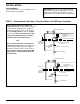
TO BURNER
LINE
13
4
4
3
2
1
COMMON
CLOSING CIRCUIT
OPENING CIRCUIT
NO. 7B
SWITCH
BLUE
RED
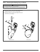
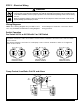
Proportional Control, Low Water Cut-Off and Alarm
2 4
1 3
BLUE
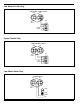
BURNER ON–ALARM OFF
VALVE CLOSED
BURNER ON–ALARM OFF
VALVE OPEN
BURNER OFF–ALARM ON
VALVE OPEN
RED
3 1
4
2 4
1 3
BLUE
RED
3 1
4
2 4
1 3
BLUE
RED
3 1
4
NOTE: The 7B switch is a 135 ohm potentiometer slide
wire control for use with an electric valve operator with
the same rating.
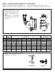
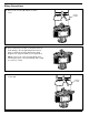
For Series 93/193 or 94/194 with 7B or 7B-M
Red terminals 1 and 2 are the burner circuit contacts, terminals 3 and 4 are the low level alarm circuit
contacts.
Blue terminal 3 is the common contact, terminals 1 and 4 are the output contacts.