
Install Instructions


Power
Model Voltage** Consumption*
WFE-24 24VAC 15VA
WFE-120 120VAC 20VA
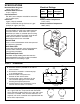
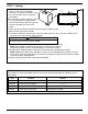
WATER FEEDER
INLET
VALVE
OUTLET
VALVE
UNION
UNION
STRAINER
CITY
WATER SUPPLY
CHECK
VALVE
BYPASS
VALVE
UNION
BYPASS
CONNECT TO
RETURN HEADER
ON BOILER
2
1a. Control must be installed within eyesight of boiler.
b. Clearance must be provided on all sides to
service control.
c. Unit must be installed in a horizontal pipe
in an upright position.
d. Arrow on feeder must point in the
direction of flow into the boiler.
e. Install isolation valves and unions on the
inlet and outlet piping for easier trouble
shooting and repair/replacement.
f. Install manual fill valve and bypass line for
removal while the boiler is in service.
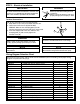
2. Water feeders are shipped from the factory equipped
for a 2 gpm feed rate. A separate kit with instruction
sheet and field installable orifices for 1 gpm and 4 gpm
feed rates is included. If the alternate feed rates are
required, refer to the instruction sheet provided with the
kit for orifice replacement.
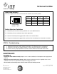
1 GPM
Orifice
4 GPM
Orifice
Dwell/Feed
Selector Switch
Multi
Function
LED
Manual
Feed
Button
2
3
4
1
ON
SW1
OFF
SPECIFICATIONS
Maximum Water Pressure:
150 psi (10.5 kg/cm
2
)
Maximum Boiler Pressure:
15 psi (1 kg/cm
2
)
Pipe Connections:
3/8" NPT (sweat adapters included for connection
to 1/2" copper pipe)
Flow Data:
2 gpm (7.6 lpm) standard
Orifices included to change feed rate to 1 gpm
(3.8 lpm) or 4 gpm (15.1 lpm)
Maximum Water Temperature:
175˚F (79˚C)
Maximum Ambient Temperature:
100˚F (38˚C)
Dwell/Feed Selector Switch
The water feeder has a DIP
type switch block with
four on/off switches. Each switch has a specific
dwell/feed cycle which is activated upon receiving
a signal from the LWCO. The feeder will be deacti-
vated when the LWCO is satisfied or if the
dwell/feed period has been exceeded.
Manual Feed
There is a manual feed button which when pressed
will add water to the boiler.
Multi-Color LED
A multi-color LED indicates status during operation,
incorrect switch selection and when dwell/feed
cycle has been exceeded.
Dwell/Feed Cycle Limit
The feeder will stop feeding water whenever the
selected dwell/feed cycle time has been exceeded
and the LWCO is still sending a signal.
STEP 1 - Installation
Electrical Ratings
* During Feed Cycle
** 50/60 Hz