
Install Instructions
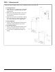
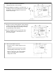

C o n t rol W i r i n g : Same vo l t age for control and burner circ u i t
• Connect hot wire to terminal 1
• Connect neutral wire to terminal 2
• Connect jumper wire from Te r minal 1 to Te r minal 3
• Connect wire from beginning of Burner circuit
( t h e r mostat, gas va l ve, limits, etc.) to terminal 5
• Connect wire from end of Burner circuit to terminal 2
To prevent electrical fire or equipment damage,
electrical wiring must have a rating of 167°F
(75C) if the liquid's temperature exceeds
180°F (82°C).
Failure to follow this warning could cause
property damage, personal injury or death.
WARNING
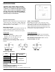
STEP 5 - Electrical Wiring
Boiler manufacturer schematics should alw a ys be fo l l ow e d.
In the event that the boiler manufacturer's schematic does
not exist, or is not available from the boiler manufacturer,
refer to the schematics provided in this document.
IMPORTANT
Probe wires should be minimum 18 AWG stranded
with glass braided Silicone jacket (UL 3071) suitable
for high temperature (200°C) service.
NOTE
Wiring Diagram Legends
1 . Bold lines indicate action to be taken in Step show n .
2 . Dotted bl a ck lines indicate internal wiri n g .
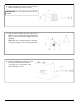
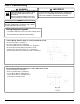
C o n t rol W i r i n g : D i f f erent vo l t a ge for control and burner circ u i t
• Connect hot wire to terminal 1
• Connect neutral wire to terminal 2
• Locate Boiler Burner Safety Circuit
and connect wires to Te r minals 3 & 5
as shown to interrupt circuit
6