
Install Instructions
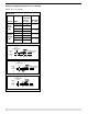
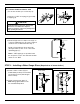
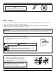

a. Using a pipe wrench, unscrew the plastic
float blocking plug (A) from the low water
cut-off body (B).
5
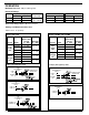
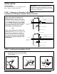
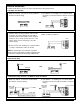
If the control will be the primary low
water fuel cut-off, size the steam (top)
and water (bottom) equalizing pipe lengths
so that the horizontal cast line on the body
is 1a” (35mm) below the boiler’s normal
water level, but not lower than the lowest,
safe permissible water level, as deter-
mined by the boiler manufacturer.
OR
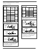
If the control will be the secondary low
water fuel cut-off, size the steam (top) and
water (bottom) equalizing pipe lengths so
that the horizontal cast line on the body is
at or above, the lowest, safe permissible
water level, as determined by the boiler
manufacturer.
STEP 2 - Installing the Low Water Cut-Off
STEP 1 - Determine the Elevation at Which the
Low Water Cut-Off/Pump Controller Must be Installed
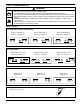
INSTALLATION
TOOLS NEEDED:
Two (2) pipe wrenches, one (1) flathead screw
driver, and pipe sealing compound.
IMPORTANT: Follow the boiler manufacturer's
instructions along with all applicable codes and
ordinances for piping, blow down valve and water
gauge glass requirements.
1
3
/8"
STEAM EQUALIZING PIPE
VERTICAL EQUALIZING PIPE
BLOW DOWN VALVE
NORMAL BOILER WATER LINE
AS A PRIMARY
LOW WATER CUT-OFF/PUMP CONTROLLER
BURNER “CUT-OFF LEVEL” AT CAST LINE
LOWEST PERMISSIBLE
WATER LEVEL
(35mm)
WATER
EQUALIZING
PIPE
STEAM EQUALIZING PIPE
VERTICAL EQUALIZING PIPE
BLOW DOWN VALVE
AS A SECONDARY
LOW WATER CUT-OFF/PUMP CONTROLLER
BURNER “CUT-OFF LEVEL” AT CAST LINE
LOWEST PERMISSIBLE
WATER LEVEL
BURNER OFF
WATER
EQUALIZING
PIPE
B
A
B
A
B
A
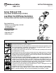
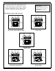
Series 150S
(except Model 150S-B)
Models 150S-B Series 157S