
Install Instructions

9
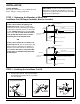
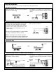
WIRING DIAGRAMS
For Motorized Valves, refer to the valve manufacturer's wiring instructions.
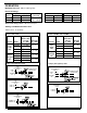
Low Water Cut-Off Only
1. Main Line Switch - For burner circuits within the
switch’s electrical rating.
1. Main Line Switch - For burner circuits within
the switch’s electrical rating.
2. Pilot Switch - To holding coil of a starter when
the burner circuit exceeds the switch’s electrical
rating.
LINE LOAD
12 456
12 456
ALARM
NEUTRAL
HOT
ALARM
NEUTRAL
HOT
12 456
12 456
SEE PUMP
CONTROL
CIRCUIT
TO NEUTRAL
TO BURNER CONTROL CIRCUIT
HOT
ALARM
12 456
LOAD
LINE (3 PHASE)
SEE PUMP
CONTROL
CIRCUIT
ALARM
12 456
LOAD
LINE
12 456
LOAD
LINE
OR
OR
OR
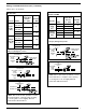
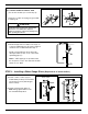
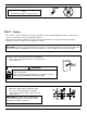
Combination Pump Control, Low Water Cut-Off and Alarm
Alarm Circuit Only
1. Low Water Alarm 2. High Water Alarm
2. Pilot Switch - To holding coil of a starter when
the burner circuit exceeds the switch’s electrical
rating.
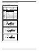
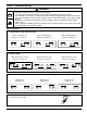
Pump Control Only
1. Install a starter or relay in pump control circuit,
as shown, to prevent damage to snap switch
and help insure proper switch/control operation.
Failure to do so may shorten the life of the
switch when actual amperage exceeds
switch rating.
2. Connect wires from holding coil of pump starter
or relay to terminals 1 and 2 as shown.
NOTE: To help insure most effective operation,
balance boiler feed pump(s) to deliver required water
feeder rate to match boiler steaming requirements.
NOTE: For Model 159S, use terminals 5 and 6 from
starter or relay for pump # 2.