
Install Instructions


INSTALLATION
2. ELECTRICAL WIRING OF NUMBER 11
SWITCH
NOTICE
Boiler manufacturer schematics should always
be followed. In the event that the boiler
manufacturer’s schematic does not exist, or is
not available from the boiler manufacturer, refer
to the schematics provided in this document.
WARNING
To prevent electrical re or equipment damage,
electrical wiring must have a rating of 167°F
(75°C) if the liquid’s temperature exceeds
180°F (82°C). Failure to follow this warning
could cause property damage, personal injury
or death.
4
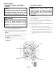
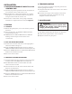
1. Remove the wiring harness from the kit box. Pre-bend
the terminal rings (GREEN wires) to 90°.
2.Usingaatbladescrewdriverremovethetwoscrews
(marked 2 and 3) on the Number 11 switch, see
Figure 5.
3. Place the terminal rings onto the 2 and 3 terminals,
re-install the screws and tightly secure.
4. Insert the RED wire connector onto terminal 1,
see Figure 5.
5. Insert the YELLOW wire connector onto terminal 4,
see Figure 5.
Figure 5
3. ELECTRICAL WIRING
3.1 GENERAL
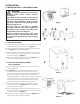
1. Install an electrical conduit to the conduit hole on
the e-11M bracket.
2. Wire-ways should be able to accommodate the
burner circuit, alarm circuit, (and the 120VAC neutral
hot wire, when applicable).
3. For all wire connections to the terminal block on the
e-11M circuit board:
• Strip about 1/3” of insulation from the wire.
• Loosen the terminal screw but DO NOT REMOVE.
Move the wire clamping plate back until the plate
touches the underside of the screw head.
• Insert the stripped end of the wire under the wire
clamping plate and securely tighten the terminal
screw.
GREEN
YELLOW
RED
GREEN
NOTICE
Follow accepted electrical practices when
installing ttings and making connections.
Refer to and follow local codes and standards
when selecting the types of electrical ttings
and conduits.