INSTRUCTION MANUAL MM-200J 245632
INSTALLATION – Model 64 – For Steam Boilers with 1” (25mm) Equalizing Lines TOOLS NEEDED: One (1) flathead screwdriver and two (2) pipe wrenches. STEP 1 - Determine the Location of the Low Water Cut-Off a. Whether the gauge glass is mounted directly into the boiler or on an independent water column, the cut-off line on the 64 body casting should be mounted 1/2" (15mm) above the lowest visible point of the gauge glass. STEP 2 - Installation of the Model 64 a.
INSTALLATION – Model 64 – For Hot Water Boilers with 1" (25mm) Equalizing Lines TOOLS NEEDED: One (1) flathead screwdriver and two (2) pipe wrenches. STEP 1 - Determine the Location of the Low Water Cut-Off a. The line on the casting of the model 64 must be installed above the lowest permissible water level determined by the boiler manufacturer. STEP 2 - Installation of the Model 64 For float type controls it is recommended that Test-N-Check® (TC-4) valves be used in the upper and lower equalizing lines.
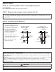
INSTALLATION – Model 764 – For Steam or Hot Water Boilers TOOLS NEEDED: One (1) flathead screwdriver and two (2) pipe wrenches. STEP 1 - For Steam or Hot Water Boilers where 2 1/2” (65mm) Tapping is Provided a. See figure 1. The 2 1/2" (65mm) tapping on the boiler has to be above the minimum safe operating level, as determined by the boiler manufacturer. On steam boilers, make sure the line on the casting is above the lower gauge glass nut.
INSTALLATION – Model 64-A – For Steam Boilers Using Quick Hook-up Fittings TOOLS NEEDED: One (1) flathead screwdriver, two (2) pipe wrenches, and an adjustable wrench. STEP 1 - Preparing the Boiler a. Remove gauge glass and its trim from the boiler. STEP 2 - Installation of the Model 64-A a. See figures 1 and 2. Install both brass Y fittings (A) into the boiler gauge glass tappings. NOTE: If gauge glass tappings are spaced more than 10 1/8" (270mm) apart, invert the Black Y (B). See figure 2.
Wiring Instructions WARNING • To prevent electrical shock, turn off the electrical power before making electrical connections. • This low water cut-off must be installed in series with all other limit and operating controls installed on the boiler. After installation, check for proper operation of all of the limit and operating controls, before leaving the site.
Diagram 1 Diagram 2 SCHEMATIC OF TWIN SWITCH INTERNAL OPERATION 10 30 02 USED AS MAIN LINE SWITCH NORMAL WATER LEVEL 4 0 NEUTRAL WIRE TO BURNER HOT WIRE 10 30 02 10 30 02 FEEDER OR ALARM OPERATING LEVEL 4 0 10 30 SAFETY SWITCH 02 0 4 HOT WIRE TO ALARM LOW WATER CUT-OFF OPERATING LEVEL 4 0 NEUTRAL WIRE Diagram 3 USED WITH MODEL 101 ELECTRIC WATER VALVE OR IN ALARM CIRCUIT NEUTRAL WIRE TO BURNER HOT WIRE 10 30 SAFETY SWITCH 02 0 4 JUMPER TO TWO WIRES OF 101A OR TO ALARM CIRCUIT
COMMERCIAL WARRANTY Warranty.