Datasheet iM980A iM980A Datasheet Document ID: D-iM980A_v1.2 mcf88 srl Via Roma 3 28060 Sozzago (NO) ITALY iM980A_Datasheet_mcf88.docx, v1.
Datasheet iM980A Document Information File name iM980A_Datasheet mcf88.docx Created 2020-09-30 Total pages 26 Revision History Version Note 1.2 Created Aim of this Document The aim of this document is to give a detailed product description including interfaces, features and performance of the radio module iM980A. iM980A_Datasheet_mcf88.docx, v1.
Datasheet iM980A Table of Contents 1. INTRODUCTION 3 1.1 Key Features 3 1.2 Applications 3 2. MODULE OVERVIEW 4 3. LORA MODULATION TECHNIQUE 5 3.1 Channel Frequencies 5 3.2 Data Rates and Spreading Factors 5 4. ELECTRICAL CHARACTERISTICS 6 4.1 Absolute Maximum Ratings 6 4.2 Global Electrical Characteristics 7 4.3 Module Interface Characteristics 8 4.4 RF Characteristics 9 4.4.1 Applicable Frequency Bands and Sub-Bands 9 4.4.2 Transmitter RF Characteristics 9 5.
Datasheet iM980A 9.4 References 10. REGULATORY COMPLIANCE INFORMATION 10.1 FCC Regulatory Notices 11. IMPORTANT NOTICE 21 22 22 25 11.1 Disclaimer 25 11.2 Contact Information 25 iM980A_Datasheet_mcf88.docx, v1.
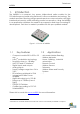
Datasheet iM980A 1. Introduction The iM980A is a compact, low power, bidirectional radio module for the 915 MHz frequency band using Semtech’s LoRaTM modulation technology. The module provides ultra-long range spread spectrum communication and high interference immunity whilst minimising current consumption. Using the iM980A in an application minimizes the need for an expensive and time-consuming RF development. Fast time to market is possible with this pre-qualified module.
Datasheet iM980A 2. Module Overview The iM980A is an ultra-long range, high-performance, pre-certified module for wireless communication. It operates in the license free 915 MHz ISM frequency band and includes all necessary passive components for wireless communication as depicted in the following figure. 32 . 768 kHz IRQ UART SPI I² C GPIO Analog Microcontroller STM32L151Cx RF Sx1272 16 MHz 32 MHz Matching Network RF 50 Ω VDD 2.4 . to 3.
Datasheet iM980A 3. LoRa Modulation Technique The iM980A uses Semtech’s LoRa proprietary spread spectrum modulation technique. This modulation, in contrast to conventional modulation techniques, permits an increase in link budget and increased immunity to inband interference. It achieves sensitivities 8 dB better than FSK modulation.
Datasheet iM980A 4. Electrical Characteristics In the following different electrical characteristics of the iM980A are listed. Furthermore details and other parameter ranges are available on request. Note: Stress exceeding of one or more of the limiting values listed under “Absolute Maximum Ratings” may cause permanent damage to the radio module. 4.1 Absolute Maximum Ratings Parameter Condition Supply Voltage (VDD) Storage Temperature Operating Temperature RF Input Power Min -0.3 -40 -40 Typ.
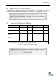
Datasheet iM980A 4.2 Global Electrical Characteristics T = 25°C, VDD = 3.0 V (typ.) if nothing else stated Parameter Condition Supply Voltage (VDD) Current Consumption Low Power Mode Current Consumption System IDLE Current Consumption RECEIVE LoRa @500kHz Current Consumption TRANSMIT Min 2.4 3.0 Max 3.6 Unit V RTC off 800 nA RTC on 1.85 µA TRX idle mode, µC idle mode 5 mA TRX receive mode, µC sleep mode 13.2 mA 122 mA 32 MHz 32.
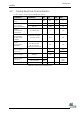
Datasheet iM980A 4.3 Module Interface Characteristics T = 25°C, VDD = 3 V (typ.) if nothing else stated Parameter Digital output voltage (high level) Digital output voltage (low level) Digital input voltage (high level) Digital input voltage (low level) Condition 2.4 V < VDD < 2.7 V, 4 mA (max) 2.7 V < VDD < 3.6 V, 8 mA (max) 2.4 V < VDD < 2.7 V, 4 mA (max) 2.7 V < VDD < 3.6 V, 8 mA (max) VDD = 2.4 V to 3.6 V, CMOS VDD = 2.4 V to 3.6 V, CMOS, 5 V tolerant Min Typ. Max - - Unit VDD -0.
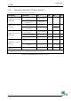
Datasheet iM980A 4.4 RF Characteristics 4.4.1 Applicable Frequency Bands and Sub-Bands Please refer to chapter 3.1 4.4.2 Transmitter RF Characteristics The iM980A has an excellent transmitter performance as given by Table 4-4. For further details, refer to Figure 4-1 which gives an overview of RF output power levels versus power level settings and its current consumption with microcontroller in sleep mode. T = 25°C, VDD = 3 V (typ.
Datasheet iM980A Figure 4-1: RF output power level and current consumption versus power stages from 1 to 20 @ room temperature and 915 MHz iM980A_Datasheet_mcf88.docx, v1.
Datasheet iM980A 5. Module Package In the following the iM980A module package is described. This description includes the iM980A pinout as well as the modules dimensions. Furthermore a recommendation for a suitable footprint is given, which should be used for further mounting on appropriate carrier boards. 5.1 Pinout Description Figure 5-1 depicts a description of the iM980A's pads on the bottom side. The figure shows the module with its pinout in top view (right figure).
Datasheet iM980A PIN PIN Name 1 2 3 4 5 6 GND P1 P2 P3 P4 GND Supply D IN/OUT D IN/OUT D IN/OUT D IN/OUT Supply PA_14 (P37) PA_13 (P34) PB_3 (P39) PA_15 (P38) Yes Yes Yes Yes - 7 nReset D IN NRST (P7) No 8 9 10 11 12 13 14 15 16 17 P5 P6 NC GND P7 P8 P9 P10 GND VDD D IN/OUT D IN/OUT NC Supply D IN/OUT, A IN D IN/OUT, A IN D IN/OUT, A IN D IN/OUT, A IN Supply Supply PA_11 (P32) PA_12 (P33) Yes Yes Yes Yes Yes Yes - Ground connection Digital IO / JTCK / SWCLK Digital IO / JTMS / SWDIO Digita
Datasheet iM980A 5.2 Module Dimensions The outer dimensions of the iM980A are given by Figure 5-2 and Figure 5-3. Figure 5-2: Outer Dimensions of the iM980A (top view) 5.3 Recommended Footprint According to Chapter 5.2, a recommendation for the footprint of the iM980A is given by Figure 5-3. Figure 5-3: Recommended footprint of the iM980A (top view) iM980A_Datasheet_mcf88.docx, v1.
Datasheet iM980A 6. 6.1 Module Interface Characteristics Programming Interface For programming the module with special firmware versions, there are two types of interfaces supported: A SWD-interface, which require a special programmer, as well as a bootloader-interface, for updating the modules firmware via UART-interface. Note: The module offers some IOs that are connected to the JTAG On-chip Debug system. Currently this interface is unavailable1.
Datasheet iM980A 7. Integration Guide The iM980A provides 32 pins as described in Chapter 5. For integrating the iM980A into an environment, a typically circuit as given in Chapter 0 can be used. While designing the PCB Layout, the recommendations of Chapter 7.2 should be applied, as well as the recommendation for soldering in Chapter 7.3. 7.1 Typical Application Schematic Figure 7-1: Typical Application Schematic for iM980A iM980A_Datasheet_mcf88.docx, v1.
Datasheet iM980A 7.2 PCB Design Recommendation The Top Layer of the carrier board should be kept free of Tracks and Vias under the iM980A because there are some test pads on the bottom side of the module which are not covered by solder resist. All GND pads of the module should be connected via low impedance path to GND. The iM980A's RF interface is already matched to 50 By using an adequate 50 antenna, no additional matching components are required1.
Datasheet iM980A Assuming a frequency of approx. 915 MHz, FR4 (er≈4.8) as substrate material, copper as conductor material, G = 0.4 mm and T = 35 µm, the width of transmission line is given by Table 7-1. H [mm] 1.0 1.6 W [mm] 1.4 1.9 Table 7-1: Recommended width of transmission line for CPWG and 915 MHz 7.3 Recommended Soldering Conditions An example of the temperature profile for the soldering process of the iM980A is depicted in Figure 7-3 with the corresponding values as given by Table 7-2.
Datasheet iM980A Note: The quality of the soldering process depends on several parameters, e.g. soldering paste, carrier board design, fabrication equipment,... iM980A_Datasheet_mcf88.docx, v1.
Datasheet iM980A 8. Ordering Information Ordering Part Number Description iM980A Radio Module 128 KB Flash, 32 KB RAM, 16 MHz MCU crystal Distributor www.mcf88.it Table 8-1: Ordering Information iM980A_Datasheet_mcf88.docx, v1.
Datasheet iM980A 9. Appendix 9.
Datasheet iM980A 9.2 List of Figures Figure 1-1: Picture of iM980A ................................................................................... 3 Figure 2-1: Block Diagram of Radio Module iM980A ............................................ 4 Figure 4-1: RF output power level and current consumption versus power stages from 1 to 20 @ room temperature and 915 MHz ............................ 10 Figure 5-1: Description of iM980A module pins and top view............................
Datasheet iM980A 10. Regulatory Compliance Information The iM980A module has received Federal Communications Commission (FCC) CFR47 Telecommunications, Part 15 Subpart C modular approval in accordance with Part 15.212 Modular Transmitter Statement about FCC. 10.1 FCC Regulatory Notices Modification Statement mcf88 srl has not approved any changes or modifications to this device by the user. Any changes or modifications could void the user’s authority to operate the equipment.
Datasheet iM980A FCC Class B Digital Device Notice This equipment has been tested and found to comply with the limits for a Class B digital device, pursuant to part 15 of the FCC Rules. These limits are designed to provide reasonable protection against harmful interference in a residential installation. This equipment generates, uses and can radiate radio frequency energy and, if not installed and used in accordance with the instructions, may cause harmful interference to radio communications.
Datasheet iM980A The applicable regulation requirements are subject to change. mcf88 srl does not take any responsibility for the correctness and accuracy of the aforementioned information. National laws and regulations, as well as their interpretation can vary with the country. In case of uncertainty, it is recommended to consult the local authorities of the relevant countries. iM980A_Datasheet_mcf88.docx, v1.
Datasheet iM980A 11. Important Notice 11.1 Disclaimer mcf88 srl points out that all information in this document is given on an “as is” basis. No guarantee, neither explicit nor implicit is given for the correctness at the time of publication. mcf88 srl reserves all rights to make corrections, modifications, enhancements, and other changes to its products and services at any time and to discontinue any product or service without prior notice.