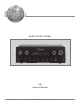
Audio Control Center C45 Owner’s Manual McIntosh Laboratory, Inc.
The lightning flash with arrowhead, within an equilateral triangle, is intended to alert the user to the presence of uninsulated “dangerous voltage” within the product’s enclosure that may be of sufficient magnitude to constitute a risk of electric shock to persons. WARNING - TO REDUCE RISK OF FIRE OR ELECTRICAL SHOCK, DO NOT EXPOSE THIS EQUIPMENT TO RAIN OR MOISTURE. IMPORTANT SAFETY INSTRUCTIONS! PLEASE READ THEM BEFORE OPERATING THIS EQUIPMENT. 1. Read these instructions. 2. Keep these instructions. 3.
Thank You Table of Contents Your decision to own this McIntosh C45 Audio Control Center ranks you at the very top among discriminating music listeners. You now have “The Best.” The McIntosh dedication to “Quality,” is assurance that you will receive many years of musical enjoyment from this unit. Please take a short time to read the information in this manual. We want you to be as familiar as possible with all the features and functions of your new McIntosh. Safety Instructions ..........................
Important Information Connector Information 1. It is recommended that a qualified professional assist you in the choice and installation of a McIntosh Audio System for your home. 2. Before making any connections to the C45, make sure that the Main POWER Switch is in the Off position. When the C45 and other McIntosh Components are in their Standby Mode the Microprocessor’s Circuitry inside each component is active and communication is occurring between them.
Introduction and Performance Features Introduction The new McIntosh C45 Audio Control Center offers a highly refined combination of useful operating features with totally transparent electronic performance. At any time expand the enjoyment and functionality of the Audio Control Center with the addition of the optional TM1 AM/FM Tuner Module installed inside the C45. Combine a C45 with a McIntosh Power Amplifier and you will enjoy a system of unparalleled performance.
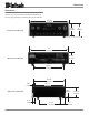
Dimensions Dimensions The following dimensions can assist in determining the best location for your C45. There is additional information on the next page pertaining to installing the C45 into cabinets. 17-1/2" 44.45cm 5-3/8" 13.69cm Front View of the C45 6" 15.24cm 17" 43.18cm 4-5/8" 11.75cm Rear View of the C45 13-1/4" 33.65cm 15-7/8" 40.32cm 5/8" 1.59cm 14-1/2" 36.83cm 3/16" 0.48cm Side View of the C45 4-13/16" 12.22cm 13/16" 2.06cm 11-1/2" 29.21cm 6 1" 2.
Installation Installation The C45 can be placed upright on a table or shelf, standing on its four feet. It also can be custom installed in a piece of furniture or cabinet of your choice. The four feet may be removed from the bottom of the C45 when it is custom installed as outlined below. The four feet together with the mounting screws should be retained for possible future use if the C45 is removed from the custom installation and used free standing.
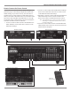
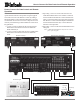
Rear Panel Connections Balanced Main OUTPUTS contain the program signals for all six channels VCR, TAPE, SAT, DVD, CD2, CD, TUNER unbalanced INPUTS accept high level program source signals Unbalanced Main OUTPUTS contain the program signals for all six channels Connect the power cord to a live AC outlet.
How to Connect for Power Control How to Connect for Power Control The three Power Control Jacks have default settings as explained on page 8. The hookup example below utilizes the default settings. If you wish to use any one of the two assignable Power Control Outputs as a dedicated Trigger instead, connect that Component Source Unit’s Power Control Input to the desired Trigger Output MAIN(A) or ACC(B). The default setting in the C45 Setup needs to be changed to match the new Power Control Connection. 1.
How to Connect for Data Control and Remote Operation How to Connect for Data Control and Remote Operation Data Control Connections facilitate the ability to remotely operate McIntosh Source Components using the supplied C45 Audio Control Center Remote Control. By adding a McIntosh Remote Control Translator/Repeater to the C45, non McIntosh Source Devices such as a Tape Deck can be remotely controlled using a McIntosh Remote Control and Keypad/Sensor. 1.
How to Connect for Two Channel Operation How to Connect for Two Channel Operation The C45 Audio Control Center has assignable Inputs. Before the Balanced and Phono Inputs can be used, they must be first selected in the Setup Mode, refer pages 15, 17 and 18. 1. Connect Audio Cables from the McIntosh C45 RF and LF Balanced OUTPUTS to the McIntosh Power Amplifier Balanced INPUTS. Note: The unbalanced RF and LF Audio OUTPUTS and unbalanced Power Amplifier Inputs may be used instead of the Balanced Connections.
How to Connect for Six Channel Operation The C45 Audio Control Center has assignable Inputs. Before the Balanced and Phono Inputs can be used they must be first selected in the Setup Mode. Refer pages 15, 17 and 18. 1. Connect Audio Cables from the McIntosh C45 Balanced LF (Left Front Channel) and the RF (Right Front Channel) OUTPUTS to the McIntosh Power Amplifier Number One Balanced INPUTS.
How to Connect for Six Channel Operation McIntosh DVD-Audio Player McIntosh CD Player McIntosh Powered Subwoofer Turntable in Tape Deck out 13
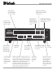
Front Panel Controls, Displays, Push-Buttons, and Switch Indicates the Sources, Volume Levels, Operational Functions, TM1 Tuner Functions and Setup Mode Settings Provides 12dB boost or cut at low frequencies with a flat center position Low impedance dynamic headphones for 2 channel listening IR Sensor for Remote Control Operation Provides 12dB boost or cut at high frequencies with a flat center position This push-button with indicator, selects either 2 Channel or 6 Channel Mode of operation when one o
Setup How to Operate the Setup Mode Default Settings Your McIntosh C45 has been factory configured for default operating settings that will allow immediate enjoyment of superb audio without the need for further adjustments. If you wish to make changes to the factory default settings, a Setup Feature is provided to customize the operating settings using the Front Panel Alphanumeric Display. 1.
Display Brightness The Front Panel Alphanumeric DISPLAY Brightness may be varied from a setting of 1 (Dim) to 15 (Bright). Follow the steps below for reducing the Display Brightness. Refer to figure 4. 1. Press the SETUP Push-button to access the Setup Mode. 2. Press the MENU Push-button until the Front Panel Alphanumeric Display indicates COUNTRY CODE. Refer to figure 7. Figure 7 Figure 4 1. Press the SETUP Push-button to access the Setup Mode. 2.
Setup, con’t Figure 10 T Push-button 3. Press the TRIM LEVEL UPS or DownT until the Front Panel Alphanumeric Display indicates “INPUT 1 *AUX”. Refer to figure 13. Note: The “*” before “AUX” indicates the default Title. Figure 11 Tuning Method TUNE - Description Allows for Manual Tuning Up or Down the radio dial. PRESETS Allows selection of a radio station preset from a previously stored station in memory. SEEK Automatically scan the dial and will stop on the next available station. 4.
6 Channel 1 and 2 Inputs Figure 15 T Push-button 6. Press the TRIM LEVEL UPS or DownT until the Front Panel Alphanumeric Display indicates “LEVEL 0.0 TUN”. 7. Rotate the INPUT Clockwise until the display indicates “LEVEL 0.0 CD2”. Refer to figure 16. Figure 16 T Push-button 8. Press the TRIM LEVEL UPS or DownT until Volume Level of the CD Input is the same as the Tuner Volume Level. Figure 17 indicates a 2.5dB decrease in the CD Level. Refer to figure 17.
Setup, con’t 3. Rotate the INPUT Control clockwise until the display indicates “BALANCED CD2”. Refer to figure 21. 4. Press the SETUP Push-button to exit the Setup Mode. 1. Press the SETUP Push-button to access the Setup Mode. 2. Press the TONE BYPASS (Menu) Push-button until “TRIG TUN > - - ” appears on the Front Panel Alphanumeric Display. Refer to figure 24. Figure 21 2 Channel Sub Figure 24 The C45 has both Balanced and Unbalanced SUBwoofer Outputs.
Setup, con’t T Push-button 3. Press the TRIM LEVEL UPS or DownT until the display indicates “AUTOTONE ON”. Refer to figure 28. Figure 28 4. Press the SETUP Push-button to exit the Setup Mode. Remote Control Selection The C45 will respond to two different sets of the Remote Control Codes. The Remote Control included with the C45 utilizes the NORMal McIntosh Control Codes. The Second Set of Control Codes the C45 will respond to is referred to as the ALTernate Codes.
How to Operate the C45 How to Operate the C45 The McIntosh C45 Audio Control Center has been factory configured for operating settings that allow immediate enjoyment of superb high fidelity audio without the need for further adjustments. If you wish to make changes to the factory default settings, refer to the SETUP Section of this Owner’s Manual starting on page 15. Power On and Off Press the POWER switch to ON, the Red LED above the STANDBY/ON Push-button lights to indicate the C45 is in Standby Mode.
TRIM push-button until the word and number “BALANCE 00” appears on the Alphanumeric Display, then press the TRIM LEVEL UpS or DownT Push-button to emphasize the Left Channel or the Right Channel. Refer to figures 35a, 35b and 41. The Front Panel Display indicates the balance changes in steps from 0 to 107. After approximately 3 seconds the Alphanumeric Display returns to the indicate the Source Selection and Volume Level.
How to Operate the C45, con’t Refer to figure 37. Note: The above condition is usually caused by either interruptions in AC power and/or major changes that may occur in AC power line voltage. Figure 37 6. Press and release the TRIM Push-button until “SURROUND 0.0” appears on the Front Panel Display. T Push-button until “SUR7. Press the LEVEL DownT ROUND -8.5” appears on the Front Panel Display. This is an example of decreasing the Center Channel Level by 8.5dB. Refer to figure 38.
Remote Control Push-Buttons LED illuminates during the time a remote command is sent to the C45 Press to Power the C45 ON or OFF Turns AC Power ON or OFF to certain McIntosh Components when connected via the Data Port Press to Power ON the C45 Press to Power OFF the C45 Selects Functions for McIntosh Home Controller and as a “shift” key when used with the AM or FM push-buttons to select Output (Spkr) 1 or 2 Selects FM Tuner Operating Functions and Track Selection on certain McIntosh CD Players Switche
How to Operate by Remote Control How to Operate by Remote Control The supplied Remote Control is capable of directly controlling the functions of contemporary McIntosh Source Components connected to the C45. Earlier McIntosh source components and other brand source components can be controlled by the C45 Remote Control with the addition of a McIntosh Remote Control Translator (RCT). Note: Your McIntosh Dealer can assist you with the installation and operation of the Remote Control Translator (RCT).
Specifications Specifications Frequency Response +0, -0.5dB from 20Hz to 20,000Hz Total Harmonic Distortion 0.002% maximum from 20Hz to 20,000Hz at rated output Signal To Noise Ratio Phono: 86dB below 10mV input (A Weighted) High Level: 96dB below rated output (A Weighted) Rated Output Voltage 2.5V Unbalanced Outputs (Main) 5.
Optional TM1 AM/FM Tuner Module TM1 AM/FM Tuner Module Cable for connecting the RAA1 to the C45 Cables for installing the McIntosh TM1 AM/FM Tuner Module into the C45 Introduction The optional McIntosh TM1 AM/FM Tuner Module can be added to the C45 Audio Control Center for Radio Broadcast Reception. The TM1 delivers the same exceptional performance as the stand-alone McIntosh MR85 Tuner. The TM1 is available from your McIntosh Dealer and can be installed at any time, usually while you wait.
Rear Panel and RAA1 Top Panel Antenna Connections RAA1 Remote Antenna can be adjusted to a position for optimum reception of your favorite AM stations Connects with supplied cable to the C45 AM ANT (Antenna) connector allows a McIntosh Remote Antenna to be connected 75ohm FM ANT (Antenna) connects to an external FM antenna or cable 28
How to Connect Antenna Components How to Connect Antenna Components 1. Connect the Remote AM antenna by plugging the DIN connector of the supplied 3 conductor cable into the AM ANT, DIN socket on the back panel of the C45. Note: If a longer length cable needs to be used between the C45 and the RAA1, use a 2 conductor shielded cable. Refer to page 4 for additional connection information. 2. Connect a 75 ohm coax cable from an FM antenna or cable system to the C45, 75 ohm FM ANT connector.
How to Operate the Tuner The McIntosh C45 TM1 AM/FM Tuner Module incorporates an advanced design AM/FM Tuner with many desirable performance features to enhance your enjoyment of radio broadcasts. There are three methods of tuning AM/FM Broadcast Stations using the Front Panel Tune Push-buttons and four methods using the Remote Control. These tuning methods include Manual, Automatic Station Seek, Automatic Preset Review, Preset Selection and Direct Preset Number Access.
How to Operate the Tuner How to Assign Tuner Presets The C45 AM/FM Tuner Module (TM1) allows for presetting radio stations into memory. Refer to figure 44 and perform the following the below steps to enter stations: Preset Number Station Frequency Broadcast Band Station FM Signal Stereo Strengh Signal 6. To verify the Station Preset(s) just entered into memory, press the the NEXTXX or BACK WW Push-button on the Remote Control to cycle through and confirm your preset assignments.
How to Optimize AM Reception The McIntosh RAA1 Remote AM Antenna is designed to provide the best in AM Reception especially if the C45 is located in a noisy reception area. Locate the RAA1 away from all electronic and electrical interference sources. Rotate the AM Antenna to reduce interference and receive maximum signal strength. Notes: The RAAI Remote AM Antenna of the TM1 has been factory adjusted for optimum reception in a typical urban location.
Notes 33
TM1 FM and AM Specifications FM Tuner Specifications AM Tuner Specifications Useable Sensitivity 14dBf which is 1.4uV across 75 ohms Sensitivity 20uV External Antenna Input 50dB Quieting Sensitivity Mono: 19dBf which is 2.4uV across 75 ohms Stereo: 35dBf which is 15uV across 75 ohms Signal To Noise Ratio 48dB at 30% modulation 58dB at 100% modulation Signal To Noise Ratio Mono: 75dB Stereo: 70dB Harmonic Distortion 0.
Packing Instructions Packing Instructions In the event it is necessary to repack the equipment for shipment, the equipment must be packed exactly as shown below. It is very important that the four plastic feet are attached to the bottom of the equipment. This will ensure the proper equipment location on the bottom pad. Failure to do this will result in shipping damage. Use the original shipping carton and interior parts only if they are all in good serviceable condition.
McIntosh Laboratory, Inc. 2 Chambers Street Binghamton, NY 13903 The continuous improvement of its products is the policy of McIntosh Laboratory Incorporated who reserve the right to improve design without notice. Printed in the U.S.A. McIntosh Part No.