
Owner`s manual


4
Important Information
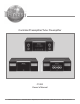
1. The C1000 System consists of two or three separate
chassis. The C1000 Controller Chassis will be referred to
as the C1000C throughout this Owner’s Manual. In a
similar manner, the C1000 Preamplifier (Solid State)
Chassis will be referred to as the C1000P and the C1000
Tube Preamplifier Chassis will be referred to as the C1000T
throughout this Owner’s Manual.
2. For additional information on Audio Connections, refer to
the Owner’s Manual(s) for the component(s).
3. Connecting Cables and Connectors are available from the
McIntosh Parts Department:
Data, Power Control and Trigger Cable Part No.
170-202
Six foot, shielded 2 conductor, with 1/8 inch stereo mini
phone plug on each end.
Controller to Preamplifier Cable Part No. 171-745
Three foot, shielded 24 conductor, male-to-male custom
cable, two required between Controller and Preamplifier.
4. The Main AC Power Cable going to the C1000C and any
other McIntosh Component(s) should not be connected to
an AC Power Outlet until all the system components are
connected together. When the C1000C and other McIntosh
Components are in their Standby Power Off Mode, the
Microprocessor’s Circuitry inside each component is active
and communication is occurring between them. Failure to
do so could result in malfunctioning of some or all of the
system’s normal operations.
5. Up to four sensors can be wired in parallel for Remote
Control of the C1000 from other rooms.
6. Balanced and Unbalanced Inputs and Outputs can be
mixed. For example, you may connect signal sources to
Unbalanced Inputs and send signals from the Balanced
Outputs. You can also use Balanced and Unbalanced
outputs simultaneously, connected to different power
amplifiers.
7. A McIntosh Power Controller may be added to the C1000 to
provide AC Power Switching to components that do not
have Power Control Connections. See your McIntosh
Dealer for additional information.
8. When the C1000P and C1000T Preamplifiers are both
connected to the same C1000C Controller ( refer to pages
20 and 21):
A. The Record Link Inputs on both preamplifiers need
to be connected together, thus allowing sharing of
their inputs for recording purposes.
B. The McIntosh MDA1000 D/A Converter may be
connected to either the C1000P or C1000T
Preamplifier.
9. Sound Intensity is measured in units called Decibels and
“dB” is the abbreviation.
10. If the C1000P and/or C1000T Preamplifiers 21 conductor
custom interconnect cable(s) become temporarily
disconnected from the C1000C when it is On or in Stand-by
Mode, a cable error message will appear on the C1000C.
Remove the AC Power Cord from the C1000C, connect the
The C1000 Preamplifiers with a Controller are the finest
audio preamplifiers McIntosh has ever created. No design
compromises were allowed in the quest for a preamplifier,
both Solid State and Tube with absolute accuracy, total
sonic purity and virtual elimination of distortion and audible
noise. For those who have been searching for the “Best in
Preamplifiers”, your wait is over.
Introduction
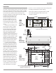
XLR Connectors
Below is the Pin configuration for the XLR Balanced Input
and Output Connectors on the C1000 Preamplifier. Refer to
the diagram for connection:
PIN 1: Shield/Ground
PIN 2: + Signal
PIN 3: - Signal
Main Power Control Connectors
The C1000’s Power Control Outputs provide a +5 volt sig-
nal. An additional connection is for
controlling the illumination of a Power
Amplifier Output Meter. Use a 1/8
inch stereo mini phone plug to connect
to the Power Control Input on other
McIntosh Components.
Trigger Control Connectors
The C1000’s Trigger Control Outputs provide either a +5
volt (default) or +12 volt signal (refer to
page 25). Use a 1/8 inch stereo mini
phone plug to connect to the Power
Control Input on McIntosh and/or non-
McIntosh components.
Data and IR Port Connectors
The C1000’s Data Port Output provides Remote Control
Signals. Use a 1/8 inch stereo mini
phone plug to connect to the Data
Port Inputs on McIntosh Source
Units.
Pin 1
Pin 2
Pin 3
Connector Information
Data Signal
N/C
Data Ground
disconnected 21 conductor custom interconnect cable(s) and
then reconnected the AC Power Cord. The C1000 System
will automatically reset itself to the previous configuration.
11. When a C1000P or C1000T Preamplifier is added to an
already existing C1000 System, the C1000C will
automatically recognize the need to re-configure the C1000
System, refer to page 41 for additional information.
Power
Control
Meter
Illumination
Control
Ground
Trigger
Control
N/C
Ground