STEREO PREAMPLIFIER C20 GENERAL DESCRIPTION TECHNICAL DESCRIPTION Mechanical Specifications Electrical Specifications FRONT PANEL FACILITIES INSTALLATION CONNECTING A-C Connections Input Connections Output Connections Ground Connections (Program Sources) TABLE OF CONTENTS OPERATING INSTRUCTIONS Balancing a Stereo System To Adjust for Balance in the Treble Range To Adjust for Amplitude Balance in the Bass Range Adjusting Phase Listening to a Stereo Record To Adjust the Balance Control After the System ha
C20 STEREOPHONIC PREAMPLIFIER GENERAL DESCRIPTION The Mclntosh C20 Stereophonic Pre-amplifier is a control center for any stereophonic sound system. This control center is necessary to accurately perform four specific functions to increase the enjoyment of stereo. is affected by variations in environment. Also, people listening to the music have varying ideas of correct tone balance. To adequately compensate for these conditions, a high-quality control center is needed.
MECHANICAL SPECIFICATIONS DIMENSIONS Chassis: 14-1/2 inches wide; 4-1/2 inches high; 12 inches deep WEIGHT Chassis: 18 pounds Shipping Weight: 28.
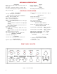
INPUT SELECTOR L . . . left channel to left speaker, no program to right speaker. INPUT SELECTOR PHONO 1 TUNER 2 S M R . . . right channel to right speaker, no program to left speaker. S PHONO 2 1 M LEFT . . . left channel only to both speakers. M M RIGHT . .. right channel only to both speakers. TAPE 1 TAPE HD AUX 2 RECORD COMPENSATOR This ten-position program switch connects the C20 as follows: AUX ...
BALANCE With the RUMBLE FILTER button pushed to the IN position, low-frequency rumble noise below 60 cps created by a turntable or changer and undesirable acoustically coupled feedback are reduced. BALANCE 0 LEFT RIGHT TAPE JACK TAPE JACK This control balances the C20 for unequal program sources. LEFT . . . turning the control to the left slowly reduces the right channel to no output and accents the left channel. RIGHT . . .
VOLUME LOW FREQUENCY TRIM VOLUME LOW FREQUENCY LEFT TRIM RIGHT OFF The combined VOLUME control and OFF-on switch controls the volume for both channels and switches line power to four black receptacles on the back panel. These controls, located on the back panel, compensate for unequal speaker response at low frequencies due to location of speakers in a room or differences in speaker efficiency.
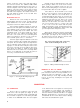
follows: Locate the center of the shelf and scribe a line from front to back. The "SHELF CUTOUT TEMPLATE" is marked for panel thicknesses from 1/4" to 1". Fold the template on the line that corresponds to the thickness of the panel. Place it on the shelf so that it butts against the inside of the panel. Match the center line mark on the template to the scribed center line on the shelf. Mark the position of the four drill holes. Drill the four 1/4" holes.
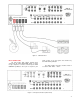
Figure 5. C20 Back Panel INPUT CONNECTIONS The C20 provides eight separate program inputs controlled by the INPUT SELECTOR switch, one input for tape comparison or monitor controlled by the TAPE COMPARE pushbutton, and a pair of telephone jack inputs located on the front panel and controlled by the TAPE JACK pushbutton. The input program connection should be made in accordance with Tables 1 and 2. Figure 6.
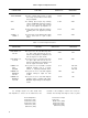
Table 1. High-Level Input Connections INPUT SENSITIVITY INPUT IMPEDANCE CONNECTION FUNCTION TAPE COMPARE The tape compare input accepts a signal from a tape recorder with a monitor head and pre-amplifier. 0.25V 115K AUX The auxiliary input accepts any auxiliary service requiring flat frequency response, such as a T.V. set, tuner, tape recorder with its own playback pre-amplifier, etc. 0.25V 470K TAPE The tape input operates with tape machines containing their own playback pre-amplifier. 0.
LEFT AMPLIFIER RIGHT AMPLIFIER Figure 9. MAIN Output Connected to Power Amplifiers The MAIN and TAPE output jacks are fed from cathode followers. The input impedance of devices connected to these outputs should be 50,000 ohms or greater, and the capacitive reactance of audio cables connecting these devices should not be less than 8,000 ohms at 20,000 cycles. This is the reactance of a capacity of 1,000 mmf. Audio cable having a capacity of 25 mmf per foot may be 40 feet long; 13.
OPERATING INSTRUCTIONS BALANCING A STEREO SYSTEM rotate RECORD COMPENSATOR control marked BASS to the TAPE position. The ultimate in stereo performance and listening enjoyment is obtained through the proper balancing of the stereo system. A properly balanced stereo system must be in phase. Each channel must be equal in loudness and similar in frequency response.
3. Set the HF CUTOFF FILTER to FLAT. 4. Set the LOUDNESS control to FLAT. 5. Rotate the INPUT SELECTOR to PHONO 1S or PHONO 2S whichever is connected to the cartridge you wish to hear. 6. Set the RECORD COMPENSATOR controls to RIAA. 7. Set the BASS and TREBLE controls to 0. 8. Place the RUMBLE FILTER pushbutton in the out position. 9. Place the TAPE COMPARE pushbutton in the out position. 10. Rotate the VOLUME (OFF-on) control to on and adjust to the desired volume.
USING THE C20 FRONT PANEL TAPE INPUT JACKS USING THE C20 WITH TAPE DECKS Two tape machines can be used with the C20 Stereophonic Preamplifier. After you have connected your tape machine to the rear panel of the preamplifier you may have someone bring in a portable machine to make a copy of one of your tapes or to listen to one of his tapes on your system. With the C20 you no longer have to unplug your permanent machine. The C20 is supplied with two cables.
Table 3. Recommended Settings of the RECORD COMPENSATOR Controls of the C20 for Monophonic Records (Cont) RECORD COMPENSATOR Manufacturer Speed BASS TREBLE (Turnover) (Roll-Off) RECORD COMPENSATOR Manufacturer 300 -5 Lyricord 33 LP LP Mercury 33 45 78 400 -12 33 RIAA -12 33 RIAA -12 New Records Oceanic Oxford 33 LP LP Period 33 RIAA LP Philharmonia 33 400 -12 Rachmaninoff Society 33 LP LP RCA Victor (Old) 33 45 78 RIAA -10 RCA Victor 33 (H.M.V.
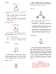
OPERATING CURVES = TAPE = RIAA = LP = 300/-5 = 400/-I0 = 0/TAPE 25 20 15 OB 10 RESPONSE IN 5 0 -5 -10 -15 -20 A TOTAL OF 25 EQUALIZATION COMBINATIONS ARE POSSIBLE, THE ABOVE SHOWS SEVERAL OF THE MOST USED CURVES. -25 20 10 KC 1 KC 100 20 KC FREQUENCY Figure 10. RECORD COMPENSATOR Controls BASS, MAX. AND MIN. RANGE 20 TREBLE, MAX. AND MIN. RANGE 15 10 RESPONSE IN D8 5 0 -5 -10 -15 -20 20 100 1KC FREQUENCY Figure 11.
0 -5 RESPONSE IN OB -10 -15 -20 -25 20 1 KC FREQUENCY 100 10 KC 20 KC 10 KC 20 KC Figure 12. RUMBLE FILTER and HF CUTOFF FILTER 0 -5 IN OB -15 RESPONSE -10 -20 -25 20 100 1 KC FREQUENCY Figure 13. LOUDNESS Control RESPONSE IN DB 10 5 0 -5 -10 Figure 14. BASE TRIM Controls—separate controls are provided for R and L outputs.
Your C20 will give you many years of pleasant and satisfactory performance. If you have any questions concerning the operation or maintenance of this pre-amplifier please contact: Customer Service Mclntosh Laboratory Inc. 2 Chambers Street Binghamton, New York Our telephone number is 723-5491. The direct dial area code is 607. GUARANTEE Mclntosh Laboratory Incorporated guarantees this equipment to perform as advertised.
LABORATORY INC. 2 CHAMBERS STREET, BINGHAMTON, N. Y. Made in U.S.A. Phone —Area Code 607-723-5491 2M-AA117-185 BE102002 Printed in U.S.A.