
User Guide


DESCRIPTION
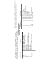
COMPONENT
NO.
Switch,
Input
Selector
Switch, Bass Compensator
Switch, Treble Compensator
Switch,
High
Frequency
Cutoff
Filter
Switch, Rumble Filter
Switch, Mode Selector
Switch,
Tape Compare
Switch, Tape Jack
Switch, Phase
Silicon Rectifier,
50 PIV at
1.6A
Transformer,
Power
S1
S2
S3
S4
S5
S6
S7
S8
S9
S1, S2
M199A
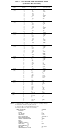
DESCRIPTION
COMPONENT
NO.
Filter Capacitor,
20/20/40
MF at
300/350/350V
Filter Capacitor,
40/40
MF at
350/350V
Filter
Capacitor,
1000/1000
MF at
15/15V
Control, Bass
Control, Treble
Control,
Loudness (Aural Compensator)
Control, Volume
— 4
Section
combined
with
power
on-off
switch
Control, Balance
Control, Bass
Trim
(Lo
Bass)
on
rear panel
C102
C103
C104
R1
R2
R 3
R4
R5
R7 (2
used)
Special
components used
in the C20 are
listed
below.
These
compo-
nents
are
designed
and
built specifically
for the
C20. They
may be
pur-
chased
directly from Customer Service, Mclntosh Laboratory Inc. When
you
Table
2.
SPECIAL
COMPONENTS
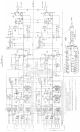
(Schematic
No.
SC119-201)
order
parts
be
sure
to
give
the
SCHEMATIC
NO. and
DESCRIPTION
from
Table
2
below,
and
serial
and
model
number
for
your amplifier.