STEREO PREAMPLIFIER C22 GENERAL DESCRIPTION 1 TECHNICAL DESCRIPTION Mechanical Specifications Electrical Specifications 1 2 2 FRONT PANEL INFORMATION 3 OPERATING INSTRUCTIONS 8 8 8 9 9 10 11 11 11 GUARANTEE 16 3-YEAR FACTORY SERVICE CONTRACT 16 INSTALLATION CONTENTS CONNECTIONS AC Connections AC Power Input Connections Output Connections Loudspeaker Phasing Connections Ground Connection OWNER'S MANUAL C 22
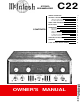
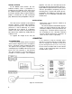
C22 STEREO PREAMPLIFIER GENERAL DESCRIPTION The Mclntosh C22 Stereophonic Preamplifier is a control center for any stereophonic sound system. To increase your enjoyment of stereo, this control center does four jobs with precise control. First, the control center amplifies weak electrical impulses. As the record rotates on the turntable, undulations in the grooves move the pickup stylus approximately one thousandth of an inch, in any direction, from the rest position.
the input preamplifier used to amplify and equalize signals from phonograph pickups, microphones or tape heads. Skillful circuit layout, proper grounding, and adequate shielding reduce the hum so low it is virtually unmeasurable. Extreme care in manufacturing combined with low noise tubes, high specific resistivity circuit boards, metal film and wire wound resistors achieves new low in residual noise.
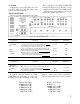
Main Output: 2.5 volts with rated input. Treble Controls: Separate channel 11 position switch type, ± 20 db at 20,000 cycles. Tape Output: .25 volts with rated input. Left Plus Right Output: 1 volt from generator impedance of 25,000 ohms. Voltage Amplification: Auxiliary, Tape, Tuner 1, and Tuner 2: To Main Output, 20 db (10 to 1). To Tape Output, 0 db (1 to 1). Phono 1 and Phono 2 (At 1 KC): To Main Output, 62 db (1250 to 1). To Tape Output, 42 db (125 to 1).
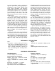
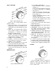
INPUT SELECTOR Figure 2. INPUT SELECTOR switch. Select any one of eight program sources with this switch: 1. AUX: any auxiliary service requiring flat amplification, such as a television set, is connected to the C22 through the AUX position. 2. TAPE: any self-contained tape machine (tape machine having its own playback preamplifier) is connected to the C22 through the TAPE position. 3. TUNER 1: AM and FM or MPX FM outputs from a stereo tuner are connected to the C22 through the TUNER 1 position. 4.
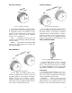
BALANCE CONTROL Figure 5. BALANCE CONTROL. Use the C22 BALANCE control to balance unequal volume in the left and right channels of a program source. The volume of each speaker system relative to the other can be varied, at the same time their combined volume level is maintained. LEFT . . . turning the control to the left accents the left channel by reducing the right channel output. RIGHT . . . turning the control to the right accents the right channel by reducing the left channel output.
for recording. PLAYBACK . . . TAPE input is switched from rear tape jacks to front panel telephone jacks (left tape and right tape). Any program originating from a portable machine connected to the C22 can be heard by rotating the INPUT SELECTOR to the TAPE position. LEFT TAPE . . . telephone jack female receptacle for the left channel of a portable tape machine. RIGHT TAPE . . . telephone jack female receptacle for the right channel of a portable tape machine. RUMBLE Figure 10. RUMBLE filter switch.
this position, additional controls on top of the C22 chassis are available; the PHASE switch, LOW FREQUENCY TRIM CONTROLS, OUTPUT LEVEL CONTROLS, TAPE EQUALIZATION CONTROLS, and the PILOT LAMP INTENSITY switch. LOUDNESS PILOT LAMP INTENSITY Use the PILOT LAMP INTENSITY to switch the front panel pilot lamps to DIM or BRIGHT. Figure 12. LOUDNESS switch. Use the LOUDNESS switch in the COMPENSATED position to listen at low volume and still hear full-frequency range.
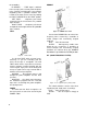
PANLOC BUTTONS At the bottom front corners are the PANLOC buttons. After a preamplifier is installed on the PANLOC shelf, depressing the PANLOC buttons will lock the preamplifier firmly in position. Depressing the PANLOC buttons a second time (as with a ball-point pen) will release the preamplifier. The pre- amplifier can then be slid forward to the inspection and adjustment position.
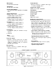
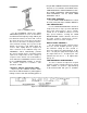
AC POWER Plug the AC power cord in 105 volt to 125 volt, 50 to 60 cycle power line. The power used by the C22 is 34 watts. INPUT CONNECTIONS The C22 provides eight separate program inputs controlled by the I N P U T SELECTOR switch. One input for tape monitor or tape comparison is controlled by the TAPE switch. The input program connections should be made in accordance with Table 1. Figure 15. INPUT CONNECTIONS. CONNECTION TAPE MONITOR (COMPARE) AUX FUNCTION INPUT SENSITIVITY INPUT IMPEDANCE 0.
Figure 16. Turntables feeding low-level inputs. OUTPUT CONNECTIONS There are two sets of outputs on the left half of the back panel. (See Figure 15) One pair is marked M A I N . The second pair is marked TAPE. The M A I N outputs connect to power amplifiers (figure 17). The TAPE output feeds a tape recorder. The MAIN jacks are fed from cathode followers. Longer cables than are normally supplied can be connected between the C22 and the amplifiers.
trols: I N P U T SELECTOR positions, AUX, TAPE, TUNER 1, T U N E R 2, or MIC, the MUTING switch and T U N I N G control. When the INPUT SELECTOR is turned to TAPE HD then the COMP should be set to R I A A . The input impedance of the tape recorder should be 50,000 ohms or greater. A jack marked L + R OUTPUT is located next to M A I N OUTPUTS. A monophonic signal can be distributed to other rooms by connecting another power amplifier to the jack marked L + R.
COMPENSATED position. 7. Place the TAPE switch in the MONITOR position. 8. Place the PHASE switch in the 0° position. 9. Place the RUMBLE filter switch in the FLAT position. 10. Place the H.F. cutoff filter switch in the FLAT position. 11. Turn the MODE SELECTOR to the L + R TO L position. 12. While the program is playing, alternate the MODE SELECTOR between the L + R TO R and the L + R TO L position.
The LOUDNESS switch on the C22 changes the VOLUME control to a loudness compensated control to correct for this effect. When you wish to listen to music at a greatly reduced loudness level and yet hear bass and treble in their proper relationships, set the LOUDNESS switch to the IN position. PHASE If the stereo sound seems to come from either side of the room instead of being distributed between the loudspeakers, adjust the PHASE control to 180°.
CONTROLS so that the dial indicators are centered between the panel markings L and R. 8. Adjust the VOLUME control to the desired volume. CONTROLS so that the dial indicators are centered between the panel markings L and R. 8. Adjust the VOLUME control to the desired volume. If the AUX input is used, turn the INPUT SELECTOR to AUX; then, proceed the same as for TAPE input. 1. Set the TAPE MONITOR switch to MONITOR. 2. Turn the MODE SELECTOR switch to MONO (L + R). 3. Set the PHASE switch to 0°. 4.
the other the only control that is effective is the TAPE JACK switch. (Note: Some portable tape machines will drive the C22 even though the TAPE JACK switch is in the RECORD position.) This is not a normal circuit use and a distorted signal usually results. For lowdistortion operation follow the recommended procedure. USING THE C22 WITH MICROPHONES FOR STEREO Microphones in stereo may be used with the C22. The two M I C channels amplify microphone signals.
Your C22 will give you many years of pleasant and satisfactory performance. If you have any questions concerning the operation or maintenance of this preamplifier please contact: Customer Service Mclntosh Laboratory Inc. 2 Chambers Street Binghamton, New York Our telephone number is 723-5491. The direct dial area code is 607. GUARANTEE Mclntosh Laboratory Incorporated guarperiod of 90 days from date of purchase, antees this equipment to perform as adverThis guarantee does not extend to compotised.
LABORATORY INC. 2 CHAMBERS STREET, BINGHAMTON, N.Y. Made in U.S.A.