
Specifications


Output Transformers
in Transistor
Power Amplifiers
by Sidney Corderman*
Output transformers can make tran-
sistor power amplifiers more reliable,
more flexible, and more powerful. At
the same time output transformers
offer the best continuous protection
to loudspeakers against the hazards of
avalanche failure of output transistor
devices.
Time has shown that output trans-
formers make transistor amplifiers
operate cool and safe. The output
transformerless amplifier (OTL)
becomes less exciting when amplifiers
must give long, consistent and predict-
able operation.
Let's take a look at transformers in
general at their past and present
use in amplifiers - - - and at why
Mclntosh Laboratory continues to be
the leader in the amplifier field with
the use of transformers.
Remember Vacuum Tube Amplifiers?
Until the early 1960's, McIntosh
and just about everyone else in the
high fidelity component manufactur-
ing business produced vacuum tube
power amplifiers exclusively. The
familiar push-pull circuit of Fig. 1
reigned supreme. In that circuit we
had a pair of tetrode or pentrode tubes
with their high output impedance try-
ing to deliver power to low impedance
loudspeaker systems. A transformer
was needed to provide the necessary
impedance match between them. But
there were problems in trying to
achieve an optimum transfer of power
between tubes and speakers. Typically,
using a pair of 6L6 output tubes in
push pull, we had a tube load imped-
ance of 4000 ohms trying to deliver
Fig. 1 — Typical push — pull output circuit
(see story tor dashed line information)
power to, say, an 8 ohm speaker load.
The impedance ratio was 500 to 1,
and the necessary transformer had to
have a turns ratio of around 23 to 1
(turns ratio varies as the square root of
the impedance ratio). The required
turns ratio created problems at both
ends of the audio frequency spectrum.
Leakage inductance and shunt capaci-
tance (represented as dashed lines in
Fig. 1) caused high frequency roll-off.
The primary inductance of the trans-
former together with its inherent non-
linear characteristics placed limits on
low-frequency response. And the
energy stored in the unwanted leakage
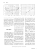
inductance caused notch distortion, as
illustrated in Fig. 2.
Fig. 2 - Notch distortion in a typical Class B
output circuit
The McIntosh Unity Coupled Circuit
Long before the advent of tran-
sistorized power amplifiers, McIntosh
found an effective way to solve these
problems. We called it the Unity Cou-
pled Circuit. The basic configuration
is illustrated in the diagram of Fig. 3.
Fig. 3 — McIntosh "notch free" low
distortion Unity Coupled Circuit
*
Vice President of Research and Development, McIntosh Laboratory Inc.
8