
Specifications


THE MCINTOSH POWER GUARD
The Power Guard waveform comparison circuit
detects minute amounts of waveform difference be-
tween the output signal and the input signal. A
sampling of the program material at the output of
the amplifier is constantly compared with the pro-
gram material at the amplifier input. Should the dif-
ferences reach 1%, Power Guard goes to work.
THE MCINTOSH POWER METERS
Mclntosh developed output monitoring meters
add to your operating flexibility. Ordinary meters are
incapable of indicating the short interval informa-
tion in a sound wave. The mass of the meter move-
ment is too great to respond to the instantaneous
changes in music program material. That short inter-
val information can have a duration as brief as one-
half of one thousandth of a second. Even should the
meter be capable of the high velocity movement the
human eye could not perceive the information.
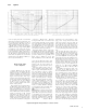
Oscillogram of output waveform with and without Power Guard.
Input overdriven for each trace 20 dB.
In only a fraction of a millisecond Power Guard
dynamically reduces input level to prevent amplifier
overload yet permits the amplifier to deliver its ab-
solute maximum power output without extra distor-
tion. In addition, the output of the "waveform com-
parator" activates the front panel NORMAL and
LIMIT indicators.
The Power Guard circuit provides a precise visual
indication when the amplifier has reached full power
output. Any time that the input circuit is fed ex-
cessive amounts of signal causing waveform dif-
ferences through the amplifier of 0.5%, the output
mode indicators change from green NORMAL to red
LIMIT automatically and instantaneously. This warn-
ing persists long enough for positive visual indica-
tion of clipping for a pulse that is so infrequent or
short that it would be impossible to be seen even on
an oscilloscope. The indicators will illuminate on
clipping for a pulse as short in time as 100 microsec-
onds. You are always assured that the power of your
amplifier is as clean and distortion free as it can be.
Mclntosh engineering pursued both problems
electrically by developing new electronic circuits
that cause the meters to respond to short interval in-
formation with an accuracy of 98%! To permit the
eye to see such high speed motion the electronic cir-
cuits that drive the meter pointer are time stretched
so the meter pointer position can register in the per-
sistence of vision characteristics of the human eye.
The meters indicate directly in watts, or can be
made to hold the highest reading and continuously
update on higher power or can be switched to be
peak reading — peak locking decibel meters.
When used as a watt indicating meter all the infor-
mation is direct reading, without conversions or
complicated mathematics. In addition, as direct
reading meters they are calibrated in average watts
for a sine wave signal but respond to signal peaks.
The meters indicate direct power in watts. They
are calibrated in average watts for a sine wave
signal but respond to signal peaks. So, a 200
average watt indication also means 400 instan-
taneous peak watts. The meters are voltage ac-
tuated and indicate power accurately when the
amplifier is operated into rated output load im-
pedances.
Watts Hold, permits the meter to lock to and in-
dicate the highest power peak in a sequence of
peaks. The meter will be driven to maximum power
and electronically held there until a higher peak
passes through the amplifier. If no further peaks are
reached the meter needle will very slowly return to a
lower peak or to its rest position at a decay rate of 10
dB per minute.
4