
Specifications


test reports
"Reprinted with permission from the June 1982 issue of STEREO REVIEW magazine.
Copyright © 1982 Ziff-Davis Publishing Company. All rights reserved."
Mclntosh MC 2255 Power Amplifier
• Mclntosh MC 2255 Power Amplifier
• Power Rating: 250 watts per channel
• Size: 16¼ x 14¾ x 7¼ inches
• Weight: 82 pounds
• Price: $2,750
T
HE Mclntosh MC 2255 basic power am-
plifier is rated to deliver its output into
loads of 1, 2, 4, or 8 ohms, from 20 to
20,000 Hz, with no more than 0.02 per cent
harmonic or intermodulation distortion. Its
stereo outputs may be paralleled or bridged
to drive a mono load with a maximum out-
put of 500 watts at 0.02 per cent distortion.
Depending on the connection used, the
mono load impedance can be from 0.5 to 16
ohms.
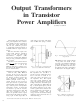
The unusual load capabilities of the MC
2255 derive from the use of large autotrans-
formers to match the output transistors to
their loads. Like vacuum-tube amplifiers,
the MC 2255 has output terminals desig-
nated for 1, 2, 4, or 8 ohms. Thus, regard-
less of the speaker impedance, the output
transistors are optimally loaded and can de-
liver
their
full
power
without
excessive
dis-
tortion or overheating.
The output stages of the MC 2255 oper-
ate in class-B, but a unique biasing system
completely eliminates the crossover distor-
tion usually associated with class-B opera-
tion. This being the most efficient mode of
linear amplifier operation, the total power
consumption of the MC 2255 from the 120-
volt a.c. line is only 0.7 ampere at idle (or
normal playing volume) and 12 amperes at
full
output.
The
input
and
driver
stages
form a complete class-AB low-power ampli-
fier which drives the front-panel headphone
jack as well as the power stages. Switches
connect the input sections for mono opera-
tion.
In the
MONO/PARALLEL
mode
the
right-channel input drives both output sec-
tions
in
phase,
and for the
MONO
BRIDGE
mode the other input section is used as a
phase inverter so that the outputs can be
driven 180 degrees out of phase.
The power stages are protected by a novel
Power Guard circuit that makes it impossi-
ble to clip the amplifier output by overdriv-
ing it. A waveform comparator monitors the
input and output signals of the amplifier,
and if the output waveform differs from the
input by an amount corresponding to about
0.5 per cent harmonic distortion, a red LIM-
IT light glows on the panel (there are sepa-
rate lights for the two channels). Any fur-
ther increase in the drive level causes the
signal to be attenuated ahead of the output
section. This prevents the output from ever
exceeding its linear operating range (ac-
cording to McIntosh, the amplifier can be
overdriven by 20 dB before distortion
reaches 2 per cent).
Internally, the McIntosh MC 2255 is a
very complex amplifier, containing some
eighty-five transistors, forty-seven diodes,
and fourteen integrated circuits. Many of
its components are involved in the protec-
tive systems and in its novel self-test fea-
ture. Each time the amplifier is turned on,
an automatic seven-step test sequence
checks the key operating voltages for cor-
rectness. As each step is executed, the cor-
responding numeral lights up on a front-
panel display and a green light signals that
it has been passed. If any stage of the test is
not satisfactory, its number remains lit to
indicate the problem area. Two different
test speeds can be selected, and one can
choose to have a "beep" sound after each
step or to have the tests proceed in silence.
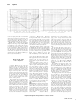
Two large meters are calibrated logarith-
mically from less than 2.5 milliwatts to 500
watts output (because of the output trans-
formers, these readings are equally applica-
ble to any of the load impedances for which
the amplifier is designed). Another scale
reads in decibels from -20 to + 2 (the lat-
ter corresponding to about 250 watts out-
put). Knobs below the meters control LEFT
GAIN, RIGHT/MONO GAIN, METER RANGE
(-20 dB, -10 dB, 0 dB, WATTS, HOLD),
the SPEAKERS outputs, and POWER. The
HOLD position of the METER RANGE switch
causes the meters to retain their highest
readings. The meter-driving circuits allow
them to respond to very short program
peaks, although they are calibrated in aver-
age watts.
At the right side of the panel are the two
indicator groups.
The
POWER GUARD
display
shows the number of the SYSTEM TEST se-
quence step as it is executed, and pairs of
red and green LEDs show either that the
LIMIT
(of
output power)
has
been exceeded
or that the amplifier operation is NORMAL.
Above this group, a meter group illuminates
the words WATTS, HOLD, or DECIBELS, ac-
cording
to the
setting
of the
METER RANGE
switch.
On the rear of the chassis are two sets of
barrier terminal strips for the speaker out-
puts, a single unswitched a.c. outlet, and the
holder for the 15-ampere line fuse. A three-
position MODE switch selects STEREO, MONO
BRIDGE,
or
MONO PARALLEL
operation. Next
STEREO REVIEW
6