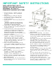
IMPORTANT SAFETY INSTRUCTIONS THESE INSTRUCTIONS ARE TO PROTECT YOU AND THE MclNTOSH INSTRUMENT. BE SURE TO FAMILIARIZE YOURSELF WITH THEM. 1. Read all instructions - Read the safety and operating instructions before operating the instrument. 2. Retain Instructions - Retain the safety and operating instructions for future reference. 3. Heed warnings - Adhere to warnings and operating instructions. 4. Follow Instructions - Follow all operating and use instructions.
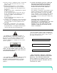
15. Nonuse Periods - Unplug the power cord from the AC power outlet when left unused for a long period of time. 16. Damage Requiring Service - Service must be performed by qualified service personnel when: A. The power supply cord or the plug has been damaged; or B. Objects have fallen, or liquid has been spilled into the instrument; or C. The instrument has been exposed to rain; or D. The instrument does not appear to operate normally or exhibits a marked change in performance; or E.
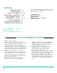
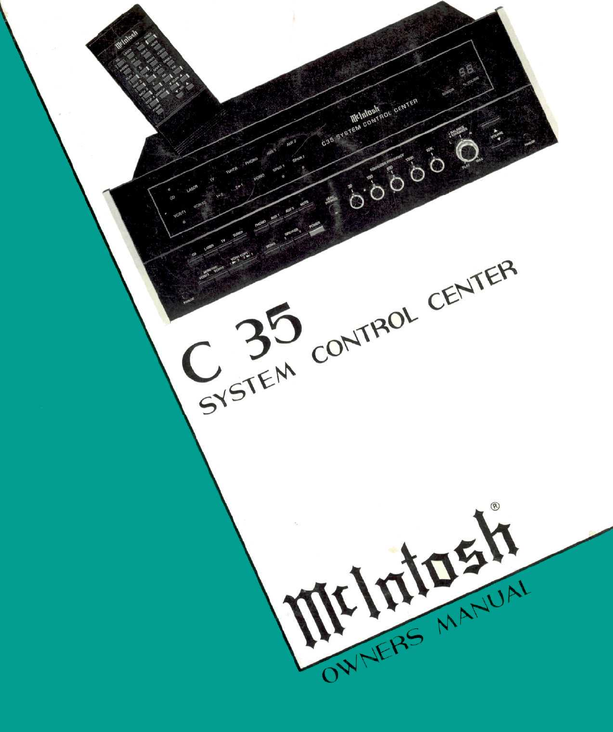
Contents INTRODUCTION INSTALLATION HOW TO CONNECT FRONT PANEL CONTROLS PERFORMANCE LIMITS PERFORMANCE CHARTS BLOCK DIAGRAM TECHNICAL DESCRIPTION CONNECTING DIAGRAM 3 4, 5 6, 7, 8 9, 10 11 12, 13 14 15 16 Your C35 System Control Center will give you many years of satisfactory performance. If you have any questions, please contact, CUSTOMER SERVICE Mclntosh Laboratory Inc. 2 Chambers Street Binghamton, New York 13903-2699 Phone: 607-723-3512 Take Advantage of 3 Years of Contract Service. . .
Mclntosh has earned world renown for its technological contributions for improved sound. When you bought Mclntosh, you bought not only high technology, you bought technological integrity proven by time. The Mclntosh C 35 System Control Center is the newest evidence of Mclntosh technological integrity. Music reproducing instruments that carry the Mclntosh name have always been designed for technological leadership and to maintain the Mclntosh reputation for best sound, for durability, and for long life.
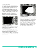
The trouble-free life of an electronic instrument is greatly extended by providing sufficient ventilation to prevent the build-up of high internal temperatures that cause deterioration. Allow enough clearance so that cool air can enter at the bottom of the cabinet and be vented from the top. With adequate ventilation the instrument can be mounted in any position. The recommended minimum space for installation is 15 inches (38.1 cm) deep, 17 inches (43.2 cm) wide, and 6 inches (15.2 cm) high.
4. Saw the Panel Cutout Saw carefully on the inside of the penciled lines, First make the two long cuts and then the two short cuts. After the rectangular opening has been cut out, use a file to square the corners and smooth any irregularities in the cut edges. 5. Install the Mounting Strips In the hardware package are two mounting strips, and two 1-1/4" (31.8mm) black long screws that have a flat head. Use these screws, one on each end, to fasten the mounting strips.
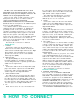
be connected to the TV INPUT. Connect the left channel cable to the Left TV INPUT. Connect the right channel cable to Right TV INPUT. The output of a monophonic TV set can be connected to both left and right channel TV INPUTS by use of a "Y" connector. The back cover of this manual folds out to show photographs of the front and rear panels of the C 35. Fold it out to assist you in locating the connectors. The numbers refer to the paragraphs that follow.
shielded cables with XLR type connectors to connect between the preamplifier and the power amplifier. When using 2 conductor shielded cables with XLR type connectors, connect the BALANCED OUTPUT LEFT of the preamplifier into the left XLR connector on the power amplifier. Connect the BALANCED OUTPUT RIGHT on the preamplifier to power amplifier right XLR connector. Pin configuration of the XLR connectors is: PIN 1: Shield ground PIN 2: + OUT PIN 3: - OUT.
provide additional capacity of 1800 watts which is controlled by the AC power switch on the C 35. Use these outlets to supply AC power to amplifiers or other components when the total load switched exceeds the C 35 rating of 1500 watts. Plug the computer-type connector on the cable attached to the SCR 3 into the SCR socket on the rear of the C 35. Plug the SCR 3 heavy, AC power line cord directly into a wall outlet. Do not plug it into the C 35.
The back cover of this manual folds out to show photographs of the front and rear panels of the C 35. Fold it out to assist you in identifying and locating the controls on the photographs. The letters refer to the paragraphs that follow. The glass upper half of the C 35 front panel is the message center. It illustrates the source, volume setting, mode of operation, tape facilities in use, and connected operating speakers.
G. SPEAKER 1 and 2 The SPEAKER 1 and 2 buttons can be used to switch on or off either the SWITCHED 1 and 2 AUDIO OUTPUTS jacks or the main and remote speakers when an optional SPEAKER CONTROL RELAY (SCR 3} is used. The SWITCHED 1 and 2 jacks on the rear panel of the C 35 have the same program as the MAIN OUTPUT. When one or both SPKR1 and SPKR2 indicators are lighted in the message center, the program is connected to the corresponding AUDIO OUTPUTS jacks.
PERFORMANCE LIMITS Performance limits are the maximum deviation from perfection permitted for a Mclntosh instrument. We promise you that when you purchase a new C 35 from a Mclntosh franchised dealer, it will be capable of or can be made capable of performance at or exceeding these limits or you can return the unit and get your money back. Mclntosh is the only manufacturer that makes this statement. FREQUENCY RESPONSE + 0, -0.
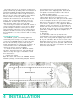
EQUALIZE R FREQUENCY RESPONSE CONTROLS SET AT M AXlMUM AND MINIMUM 20 RESPONSE IN dB 10 0 -10 20 100 1K FREQUENCY IN HERTZ 10K 20K FREQUENCY RESPONSE HIGH LEVEL IN TO MAIN OUT LOUDNES S CONTROL RESPONSE FOR VARI OUS CONTROL POSITIONS 20 15 RESPONSE IN dB RESPONSE IN dB 0 10 5 -1 -2 -3 -4 -5 -6 -7 0 20 100 1K FREQUENCY IN HERTZ 10K 20K 100 1K FREQUENCY IN HERTZ 12 PERFORMANCE CHARTS 10K 20K
RESPONSE IN dB RIAA EQUALIZATION CURVE 10 0 -10 -20 1K 100 20 10k 20K FREQUENCY IN HERTZ HARMONIC DISTORTION AUX IN TO MAIN OUT HARMONIC DISTORTION IN PRECENT 0.05 0.04 0.03 0.02 0.
14 BLOCK DIAGRAM
FULL ELECTRONIC SWITCHING All signal switching including input tape, tape-totape, and mono is done elctronically using J-FET field effect analog switches. All the front panel switches control small amounts of DC voltage which turn the FET analog switches on and off. The critical audio signals are switched silently with instantaneous muting between switch positions. No transient switching noises or pops are present with this superior design.
C 35 TYPICAL SIMPLIFIED CONNECTIONS TIME DELAY POWER AMPLIFIER AUDIO TAPE 2 VCR TIME DELAY OR REAR SPEAKERS AUDIO TV TAPE 1 AUDIO VCR SECOND AREA SPEAKERS MAIN SPEAKERS LASER VISION PLAYER OTHER HIGH LEVEL SOURCE OTHER HIGH LEVEL SOURCE SECOND AREA POWER AMPLIFIER MAIN POWER AMPLIFIER BALANCED MAIN OUTPUT TO MAIN POWER AMPLIFIER SIGNAL PROCESSOR TO MAIN OUTPUT SIGNAL PROCESSOR TO TAPE OUTPUT CD TURNTABLE TUNER CONTROL CABLE FOR MVS-1 VIDEO SELECTOR (OPTIONAL) CONTROL CABLE FOR IR CONTR
THE LOCATION OF CONTROLS The numbers and letters correspond to the paragraphs on pages 6, 7, 8, 9 and 10