
Operating instructions
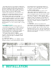

The back cover of this manual folds out to show
photographs of the front and rear panels of the C 35.
Fold it out to assist you in locating the connectors. The
numbers refer to the paragraphs that follow.
There are four fields of audio connectors on the
back panel of the C 35 for use with associated
equipment: AUDIO INPUTS, EXTERNAL
PROCESSORS, AUDIO OUTPUTS, and BALANCED
OUTPUTS. On the front panel is an additional phone
jack for use with headphones.
Use shielded cables to interconnect the source
equipment and the preamplifier. To minimize the
possibility of hum or noise, the shielded cables
should be of parallel construction or, if not, loosely
twist the left and right cables together. Locate them
away from the speaker connecting cables and AC
power cords. Be certain to use good quality shielded
cables for all interconnections. Your dealer can
advise you on the kind and length of cable that will
best suit your installation.
The first field of connectors is marked:
AUDIO INPUTS
1. PHONO:
Connect the cable from the turntable left
channel to the Left Phono INPUT. Connect the
cable from the turntable right channel to the Right
PHono INPUT. If the turntable has a separate
ground lead, connect it to the screw terminal
marked ground (GND).
2. GND (ground):
The ground (GND) post on the rear panel is
provided primarily for grounding a turntable or
record changer that has a separate ground lead in
addition to the signal leads.
3. CD:
Connect the cable from the Compact Disc (CD)
player left channel output to the Left CD INPUT.
Connect the cable from the CD player right
channel output to the Right CD INPUT.
4. LASER VISION PLAYER:
The audio from a laser vision video disc player
can be connected to the LASER INPUT. Connect
the cable from the left channel audio output of a
laser disc player to the Left LASER INPUT. Connect
the cable from the right channel audio output of a
laser disc player to the Right LASER INPUT.
5. TV:
Audio from a stereo TV set or TV monitor can
be connected to the TV INPUT. Connect the left
channel cable to the Left TV INPUT. Connect the
right channel cable to Right TV INPUT.
The output of a monophonic TV set can be
connected to both left and right channel TV
INPUTS by use of a "Y" connector.
6. TUNER:
Connect the cable from the tuner left channel
output to the Left TUNER INPUT. Connect the
cable from the tuner right channel output to the
Right TUNER INPUT.
7. AUX 1 AND 2:
Audio from any high level source is connected
to AUX 1 or 2 INPUTS. Connect a cable from the
left channel audio output of a TV monitor or other
high level source, to the Left AUX 1 INPUT jack.
Connect a cable from the right channel audio
output to the Right AUX 1 INPUT jack. AUX 2 may
be used in a similar manner.
8. VCR 1/TAPE 1:
For tape playback or to monitor while recording:
connect a cable from the tape recorder left chan-
nel output to the Left VCR 1/TAPE 1 INPUT. Con-
nect a cable from the tape recorder right channel
output to the Right VCR 1/TAPE 1 INPUT. Connect
a second recorder in the same manner to the VCR
2/TAPE 2 INPUT.
Video Tape Recorders: If you prefer, one or both
of the VCR/TAPE INPUTS can be used for the
audio from a VCR. Connect the left channel audio
output from the VCR to the Left VCR 1/TAPE 1
INPUT. Connect the right channel audio output
from the VCR to the Right VCR 1/TAPE 1 INPUT. If
the VCR has only a single audio output (mono),
use a "Y" connector to connect the program to
both the left and right input.
The second field of connectors is marked:
EXTERNAL PROCESSORS
9. EXTERNAL PROCESSORS
There are two sets of EXTERNAL PROCESSOR
jacks. The TAPE set affects the program fed to the
VCR/TAPE 1 and 2 OUTPUT jacks and the MAIN
set affects the program fed to the AUDIO OUT-
PUTS MAIN and SWITCHED 1 and 2 jacks. Use the
EXTERNAL PROCESSOR jacks to add a noise
reduction or any audio signal processing device.
Be sure to match the left to left and right to right
channels when connecting external processors.
The EXTERNAL PROCESSOR-FROM jacks have
6 HOW TO CONNECT