
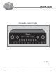
Owner`s manual


4
Table of Contents
Safety Instructions ............................................................ 2
Thank You and Please Take a Moment ............................. 3
Technical Assistance and Customer Service ..................... 3
Table of Contents and Important Information ................... 4
Connector Information ...................................................... 4
Introduction ....................................................................... 5
Performance Features ....................................................... 5
Dimensions ........................................................................ 6
Installation ........................................................................ 7
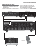
Connections
Rear Panel Connections ..................................................... 8
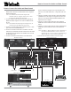
How to Connect for Power Control ................................... 9
How to Connect for Audio and Data Control ................... 10
How to Connect for a Second Room ................................ 11
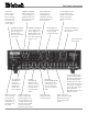
Front Panel Features
Front Panel Controls, Displays, Push-buttons,
and Switches .................................................................... 12
Setup
How to Operate the Setup Mode ...................................... 13
Default Settings ................................................................ 13
Display Brightness ........................................................... 13
Re-Title Inputs ................................................................. 14
Input Trim Level .............................................................. 14
Auto Tone......................................................................... 15
Remote Control Selection ................................................ 15
Firmware Version ............................................................. 15
Operation
Remote Control Push-buttons .......................................... 16
How to Operate by Remote Control ................................. 17
How to Operate the C46 .................................................. 18
Notes ................................................................................ 21
Additional Information
Specifications and Performance Chart ............................. 22
Packing Instruction .......................................................... 23
Important Information
1. Connecting Cable is available from the McIntosh Parts
Department:
Data and Power Control Cable Part No. 170-202
Six foot, shielded 2 conductor, with 1/8 inch stereo mini
phone plug on each end.
2. For additional information on Audio Connections, refer to
the Owner’s Manual(s) for the component(s).
3. The Main AC Power going to the C46 and any other
McIntosh Component(s) should not be applied until all the
system components are connected together. When the C46
and other McIntosh Components are in their Standby Power
Off Mode, the Microprocessor’s Circuitry inside each
component is active and communication is occurring
between them. Failure to do so could result in
malfunctioning of some or all of the system’s normal
operations.
4. Up to four Sensors can be wired in parallel for Remote
Control of the C46 from other rooms.
5. Balanced and Unbalanced Inputs and Outputs can be
mixed. For example, you may connect signal sources to
Unbalanced Inputs and send signals from the Balanced
Outputs. You can also use Balanced and Unbalanced
Outputs simultaneously, connected to different Power
Amplifiers.
6. A McIntosh Power Controller may be added to the C46 to
provide AC Power Switching to components that do not
have Power Control Connections. See your McIntosh
Dealer for additional information.
7. Sound Intensity is measured in units called Decibels and
“dB” is the abbreviation.
8. The Number 1 Input of the C46 allows for connection of
either a High Level Source (such as a second Tuner) or a
Low Level Source (such as a turntable with a moving
magnet cartridge). The slide switch located between the
AUX and PHono Jacks on the Rear Panel determines which
Inputs Jacks become active. The Default Title for the
Number 1 Input that appears on the Front Panel
Alphanumeric Display is AUX. If the Number 1 Input switch
is set to the PHono, the Title may be changed by going into
the Setup Mode and renaming the Input. Refer to page 14.
XLR Connectors
Below is the Pin configuration for the XLR Balanced Input
and Output Connectors on the C46. Refer to the diagram
for connection:
PIN 1: Shield/Ground
PIN 2: + Input
PIN 3: - Input
Power Control and Trigger Connectors
The C46’s Power Control Outputs provide a 5 volt signal.
Use a 1/8 inch stereo mini phone
plug to connect to the Power Con-
trol Input on other McIntosh Com-
ponents.
Data Port Connector
The C46’s Data Port Output provides Remote Control Sig-
nals. Use a 1/8 inch stereo mini
phone plug to connect to the Data
Port Inputs on McIntosh Source
Units.
Connector Information
Positive
N/C
Ground
Pin 1
Pin 2
Pin 3
Data Signal
N/C
Ground