
Owner`s manual


7
Installation
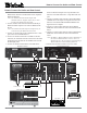
The C46 can be placed upright on a table or shelf, standing
on its four feet. It also can be custom installed in a piece of
furniture or cabinet of your choice. The four feet may be
removed from the bottom of the C46 when it is custom in-
stalled as outlined below. The four feet together with the
mounting screws should be retained for possible future use
if the C46 is removed from the custom installation and used
free standing. The required panel cutout, ventilation cutout
and unit dimensions are shown.
Always provide adequate ventilation for your C46. Cool
operation en-
sures the longest
possible operat-
ing life for any
electronic instru-
ment. Do not
install the C46
directly above a
heat generating
component such
as a high pow-
ered amplifier. If
all the compo-
nents are in-
stalled in a
single cabinet, a
quiet running
ventilation fan
can be a definite
asset in main-
taining all the
system compo-
nents at the
coolest possible
operating tem-
perature.
A custom
cabinet installa-
tion should pro-
vide the follow-
ing minimum
spacing dimen-
sions for cool
operation. Allow
at least 2 inches
(5.08cm) above
the top, 2 inches
(5.08cm) below
Installation
4 -7/8"
12.38cm
17-1/16"
43.34cm
Cutout Opening for Custom Mounting
C46 Front Panel
Custom Cabinet Cutout
14"
35.56cm
14"
35.56cm
15-1/16"
38.26cm
17/32"
1.35cm
Cutout Opening
for Ventilation
Cutout Opening for Ventilation
Support
Shelf
Cabinet
Front
Panel
Chassis
Spacers
C46 Side View
in Custom Cabinet
C46 Bottom View
in Custom Cabinet
1"
2.54cm
the bottom and 1 inch (2.54cm) on each side of the Audio
Control Center, so that airflow is not obstructed. Allow 19-
1/2 inches (49.53cm) depth behind the front panel. Allow 1-
1/8 inch (2.9cm) in front of the mounting panel for knob
clearance. Be sure to cut out a ventilation hole in the mount-
ing shelf according to the dimensions in the drawing.