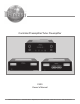
Controller/Preamplifier/Tube Preamplifier C500 Owner’s Manual McIntosh Laboratory, Inc.
The lightning flash with arrowhead, within an equilateral triangle, is intended to alert the user to the presence of uninsulated “dangerous voltage” within the product’s enclosure that may be of sufficient magnitude to constitute a risk of electric shock to persons. WARNING - TO REDUCE RISK OF FIRE OR ELECTRICAL SHOCK, DO NOT EXPOSE THIS EQUIPMENT TO RAIN OR MOISTURE. IMPORTANT SAFETY INSTRUCTIONS! PLEASE READ THEM BEFORE OPERATING THIS EQUIPMENT. 1. Read these instructions. 2. Keep these instructions. 3.
Thank You Table of Contents Your decision to own this McIntosh C500 Controller together with the Preamplifier or Tube Preamplifier ranks you at the very top among discriminating music listeners. You now have “The Best.” The McIntosh dedication to “Quality,” is assurance that you will receive many years of musical enjoyment from this unit. Please take a short time to read the information in this manual. We want you to be as familiar as possible with all the features and functions of your new McIntosh.
Important Information WARNING: The McIntosh C500 is a two chassis design, with separate Preamplifier and Controller chassis. There are custom interconnecting cables and custom chassis sockets used to connect the two chassis together. Use ONLY the custom interconnect cables supplied with the C500 to connect the chassis together. DO NOT connect the C500 Left and Right 25Pin Chassis Sockets to any other component. Failure to observe the above warnings will result in damage to the components connected. 1.
Introduction and Performance Features Performance Features • Dual Chassis with Dual Mono Design The Dual Chassis design completely separates all power supply, microprocessor and control circuits from the pure audio circuits for total noise isolation. To further aid in channel isolation the circuitry for both channels is totally separate, physically isolated and shielded. The C500 incorporates two identical power supplies one for each channel, to help assure total channel isolation.
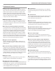
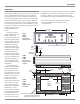
Dimensions The following dimensions can assist in determining the best location for the C500 Controller, C500 Preamplifier and C500 Tube Preamplifier. There is additional information on page 8 pertaining to installing the C500 System into cabinets. 17-1/2" 44.45cm 5-3/8" 13.69cm Front View of the C500C 6" 15.24cm 17-1/16" 43.34cm 4-5/8" 11.75cm Rear View of the C500C 13-1/4" 33.65cm 18-3/8" 46.67cm 5/8" 1.59cm 17" 43.18cm 3/16" 0.48cm Side View of the C500C 12.22cm 13/16" 2.
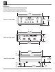
Dimensions 17-1/2" 44.45cm 5-3/8" 13.69cm Front View of the C500P 6" 15.24cm 17-1/16" 43.34cm 4-5/8" 11.75cm Rear View of the C500P 13-1/4" 33.65cm 18-3/8" 46.67cm 17" 43.18cm 3/16" 0.48cm Side View of the C500P 4-13/16" 12.22cm 13/16" 2.06cm 3" 12-5/8" 7.62cm 32.07cm 1-3/8" 3.
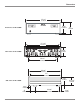
Dimensions, con’t 17-1/2" 44.45cm 5-3/8" 13.69cm Front View of the C500T 6" 15.24cm 17-1/16" 43.34cm 4-5/8" 11.75cm Rear View of the C500T 13-1/4" 33.65cm 18-3/8" 46.67cm 17" 43.18cm 3/16" 0.48cm Side View of the C500T 12.22cm 13/16" 2.06cm 8 4-13/16" 3" 12-5/8" 7.62cm 32.07cm 1-3/8" 3.
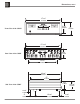
Installation Installation The C500C, C500P and C500T can be placed upright on a mounting panel for clearance. When the C500C, C500P and table or shelf, standing on their four feet. The four feet, may C500T are to be installed in cabinets refer to the illustrabe removed from the bottom of the C500C, C500P and tion below . Be sure to cut out a ventilation hole in the C500T when they are custom installed as outlined below. mounting shelf according to the dimensions in the drawing.
Notes 10
Rear Panel Connections Rear Panel Connections The identification of Rear Panel Connections for the C500 Controller, C500 Preamplifier and C500 Tube Preamplifier are located on separate folded sheets contained in the Owner’s Manual Packet.
How to connect the C500 This page contains information for connecting the McIntosh C500C to the C500P or C500T and to other audio components. The C500 has the ability to automatically switch power On/Off to McIntosh Source Components via the Power Control Connections. The Data Port Connections allow for the remote operation of basic functions using the C500 Remote Control.
How to connect the C500 19. Connect Cables from the External Sound Processor Left and Right Outputs to the C500 Preamplifier PROCESSOR FROM LEFT and RIGHT Input Jacks. 20. Connect Cables from the Music Server Left and Right Outputs to the C500 Preamplifier Unbalanced SRVR (4) LEFT and RIGHT INPUTS Jacks. 21. Connect Cables from the Music Server Left and Right Inputs to the C500 Preamplifier Unbalanced SRVR (4) LEFT and RIGHT OUTPUTS Jacks. 22.
C500 Controller Front Panel Controls, Displays, and Push-Buttons RECORD Switch selects the program signals that are available to record from and is used for setup functions BALANCE Control allows the adjustment of the relative volume levels for each channel and is used for setup functions LISTEN Switch selects the program signals that are listened to and is used for setup functions DISPLAY indicates the Listen and Record Sources, Listening Volume Level and Setup Functions IR Sensor for Remote Control Op
C500 Preamplifier and C500 Tube Preamplifier Front Panel Displays and Jack METER indicates the Preamplifier’s Left Channel relative Output Level METER indicates the Preamplifier’s Right Channel relative Output Level HEADPHONES jack accepts dynamic headphones METER indicates the Preamplifier’s Left Channel relative Output Level METER indicates the Preamplifier’s Right Channel relative Output Level HEADPHONES jack accepts dynamic headphones 15
How to Operate the Setup Modes Your McIntosh C500 has been factory configured for default operating settings that will allow immediately enjoyment of superb audio without the need for further adjustments. If you wish to make changes to the factory default settings, a Setup Feature is provided to customize the operating settings using the Front Panel Alphanumeric Display on the C500C Controller.
Setup 7. To exit from the Setup Preamp Mode press the SETUP Push-button, the LED above the SETUP Push-button will extinguish and the Front Panel Display will revert back to its normal display. Refer to figure 3. 4. If no other adjustments are to be made at this time, press the SETUP Push-button to exit the Setup Controller Mode or proceed to the next desired Setup Controller Mode for adjustment.
3. Rotate the SELECT 2 Control counterclockwise until the Front Panel Alphanumeric Display indicates REMOTE HR054. Refer to figure 9B. Figure 12 Figure 9B 4. If no other adjustments are to be made at this time, press the SETUP Push-button to exit the Setup Controller Mode or proceed to the next desired Setup Controller Mode for adjustment. Meter Illumination The Front Panel Meter Illumination of the C500P or C500T Preamplifiers may be switched Off. Follow the steps below: 1.
Setup, con’t Trigger B Voltage (Power Control) The Rear Panel Trigger B Jack can provide either a 5 or 12 Volt Output when activated, with 5 Volts as the default. McIntosh Components with Power Control utilize 5 Volts; non-McIntosh components when connected to the C500C might required a higher voltage to switch them On or Off. To change the output voltage to 12 volts follow the steps below: 1.
5. Rotate the SELECT 2 Control to select On or Off for “D/A INPut 1”. 6. Rotate the SELECT 1 Control to select the next input, “D/A INPut 2”. 7. Rotate the SELECT 2 Control to select On or Off for the next “D/A INPut 2”. 8. Repeat steps 6 and7 until all seven of the MDA1000 Input Assignments have been entered into the C500 Memory. 9. Rotate the MENU Control until the words “PROG DP SUM” appears. Refer to figure 23. Figure 23 10.
Setup, con’t Source that is frequently listened to as the reference. The reference Input Source should be set to a Level of 00. Figure 29 3. Rotate the SELECT 1 Control until the desired Input Title to be changed appears in the Display, e.g. “D PORT CDR 5”. Refer to figure 29. 4. Rotate the SELECT 2 Control until the number 2 appears in the Display, e.g. “D PORT CDR 6”. Refer to figure 30. 1.
Accessory Control 10. If no other adjustments are to be made at this time, press the SETUP Push-button to exit the Setup Preamp Mode or proceed to the next desired Setup Preamp Mode for adjustment. Trigger Selection The Trigger A and B Power Control Outputs on the C500 Controller are reassignable from their default settings to activate only when a given Input(s) is selected.
Listen Processor Record Processor The C500 Preamplifier has a Listen Processor Loop for connecting an external sound processor. The Listen Processor may be assigned to be active for only those Inputs desired. To activate the Listen Proccessor Loop and assign Inputs, perform the following steps: The C500 Preamplifier has a Record Processor Loop for connecting an external sound processor. The Record Processor may be assigned to be active for only those Inputs desired.
press the SETUP Push-button to exit the Setup Preamp Mode or proceed to the next desired Setup Preamp Mode for adjustment. Figure 52 Moving Magnet Cartridge Capacitance The C500 allows the adjustment of the Moving Magnet Capacitive Loading to accommodate a wide variety of cartridge types and turntable/cabling combinations. The range of adjustment is from 50pf to 750pf in 50pf increments. To change the capacitance from the default value of 50pf setting perform the following steps: 1.
Setup, con’t and Setup Settings Charts Num ber Default Title New Title Trim Level Default Data Port New Data Port Trigger Select (A or B) Listen Processor (ON or OFF) Record Processor (ON or OFF) Passthru Input C500 Preamplifier or C500 Tube Preamplifier 1 DVD 1 2 AUX 2 3 T UNER 3 4 SRVR 4 5 CDR 5 6 CD 6 7 D/A 7 8 MM - - 9 MC - - Additional Settings Listen Processor (Present Yes or No) Record Processor (Present Yes or No) Moving Moving Coil Magnet (OHMS) (PF) Setti
Remote Control Push-Buttons LED illuminates during the time a remote command is sent to the C500 Press to Power the C500 ON or OFF Press MODE to switch the MONO Mode On or Off Turns AC Power ON or OFF to certain McIntosh Components when connected via the Data Port Selects Functions for McIntosh Home Controller and as a “shift” key when used with the AM or FM push-buttons to select Output 1 or 2 Switches OFF the entire C500 System except in Passthru Mode Use to select tuner presets, disc tracks or any num
How to Operate the Remote Control How to Operate by Remote Control The supplied Remote Control is capable of directly controlling the functions of contemporary McIntosh Source Components connected to the C500. automatic brief audition of each of the presets stored in the tuner memory. Press +10 a second time to stop on a station preset and exit the Review process. Mute Press the MUTE Push-button to mute audio. The Record Signals present at the CDR and SRVR OUTPUTS are not affected by the MUTE function.
How to Operate the C500 Power On The Red LED above the STANDBY/ON push-button lights to indicate the C500 is in Standby mode and is connected to a live AC Outlet. To switch On the C500, press the STANDBY/ON push-button. Refer to figure 64. The Alphanumeric Display will indicate the last input listened to. If this is the first time the C500 is switched on, the display will indicate “15 TUNER”, refer to figure 61.
How to Operate the C500 RECORD Selector has stopped. Refer to figure 66. Figure 66 Note: When the McIntosh MDA1000 is connected to the C500 Controller (refer to page 12) and the “D/A Control” is active (refer to the Setup Controller Mode page 19) the LISTEN Control and the INPUT Pushbuttons (W and X) on the Remote Control will step thru the active MDA1000 Inputs automatically when the D/A Input is selected.
4. To listen to the playback of the program source just recorded, rotate the LISTEN Control to the desired input. Note: The C500 RECORD OUTPUTS are not affected by the VOLUME or BALANCE Controls. To listen to a different program source while recording, turn the LISTEN Control to the desired source. The recording process will not be affected and will continue. Output Meters The C500’s Output Meters indicate the Output Voltage available at the MAIN and SPKR OUTPUT 1 & 2 Jacks to drive Power Amplifiers.
How to Operate the C500, con’t Trim Function Input Volume Trim Balance Level Mono (Stereo) Speaker 1 Speaker 2 Display Meters Moving Magnet Movig Coil Adjustment +6dB to -6dB (Left)107dB to (Right)107dB On or Off On or Off On or Off 1-7 On or Off 50pf to 750pf 25 ohms to 1,000 ohms Figure Numbers 75a and b 76 77a and b 78a and b 79a and b 80a and b 81a and b 82a and b 83a and b Figure 80a Figure 80b Figure 81a Figure 75a Figure 81b Figure 75b Figure 82a Figure 76 Figure 82b Figure 77a Figure 83a
Reset of Microprocessors In the event that the controls of the C500 stop functioning press and hold the STANDBY/ON Push-button. Three to four seconds later the Front Panel Alphanumeric Display will indicate “DETECT SYSTEM”; at this point release the STANDBY/ON Push-button. This will reset the C500 microprocessors. Refer to figure 85. Figure 85 3. Reteach the AC Power Cord. 4.
How to Operate the C500, con’t and Technical Description Technical Description McIntosh Laboratory, the company who introduced the world’s first amplifier that could be called “High Fidelity”, has done it again. The McIntosh Engineering Staff has created a Preamplifier without compromise, using the most advanced McIntosh circuit design concepts. The C500 is the third generation of a two chassis design with fully balanced circuitry that started with the introduction of the C100 in 1997.
Fully Balanced Circuitry To compliment the level of performance achieved in one of McIntosh’s famous Power Amplifiers with Quad Balanced Circuitry, the C500 Preamplifier also utilizes fully balanced cir- 34 Signal to Noise (dB) balance and freedom from control noise. The Volume Control Optical Disc on the Front Panel of Infrared LED the C500 is actually a special digital optical encoder.
Technical Description, con’t Logic Controlled Circuitry All Inputs, Outputs, Data Ports, Power Control Outputs and Trigger Outputs are controlled by Logic Circuits in the C500C. The microprocessor is the heart of the Logic Circuits and is controlled by McIntosh developed software. It implements all commands received from the Front Panel Controls or the supplied Remote Controls and indicates them on the Alphanumeric Display. Refer to figure 102.
Technical Description, con’t problems electrically. By developing electronic circuits the meters are made to respond to short intervals with an accuracy of 95%! To permit the eye to see such high speed motion, the electronic circuits that drive the meter pointer are time stretched. Special logarithmic circuitry allows the meter to indicate a 60dB plus range, without resorting to a Meter Range Switch.
Specifications C500 Preamplifier and C500 Tube Preamplifier Specifications C500 Preamplifier Specifications C500 Tube Preamplifier Frequency Response +0, -0.5dB from 10Hz to 40,000Hz Frequency Response +0, -0.5dB from 10Hz to 20,000Hz Total Harmonic Distortion 0.002% maximum from 20Hz to 20,000Hz Total Harmonic Distortion 0.
Specifications C500 Controller and General Specifications C500 Controller General Specifications Power Requirements 100 Volts, 50/60Hz at 75 watts 110 Volts, 50/60Hz at 75 watts 120 Volts, 50/60Hz at 75 watts 220 Volts, 50/60Hz at 75 watts 230 Volts, 50/60Hz at 75 watts 240 Volts, 50/60Hz at 75 watts Overall Dimensions C500C: Width is 17-1/2 inches (44.45cm) Height is 6 inches (15.24cm) including feet Depth is 24 inches (61.
Packing Instructions Packing Instructions In the event it is necessary to repack the equipment for shipment, the equipment must be packed exactly as shown below. It is very important that the four feet are attached to the bottom of the equipment. This will ensure the proper equipment location on the bottom pad. Failure to do this will result in shipping damage. Use the original shipping carton and interior parts only if they are all in good serviceable condition.
McIntosh Laboratory, Inc. 2 Chambers Street Binghamton, NY 13903 The continuous improvement of its products is the policy of McIntosh Laboratory Incorporated who reserve the right to improve design without notice. Printed in the U.S.A. McIntosh Part No.