
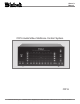
Owner`s manual


5
General Notes and Connector Information
Controller Input B (DB37 Connector):
1. Accessory-On 14. LV-Left 26. CD-Data
2. SYS-Off 15. TV-Left 27. N/C
3. Sum Data 16. Aux-Left 28. N/C
4. DVD-Data 17. Tape 1-Left 29. Ground
5. LV-Data 18. Tuner-Left 30. DVD-Right
6. Aux-Data 19. CD-Left 31. VCR-Right
7. Tuner-Data 20. Video Power 32. LV-Right
8. N/C 21. Ground 33. TV-Right
9. N/C 22. Home-Data 34. Aux-Right
10. N/C 23. VCR-Data 35. Tape-Right
11. Ground 24. TV-Data 36. Tuner-Right
12. DVD-Left 25. Tape-Data 37. CD-Right
13. VCR-Left
Controller Input A (DB25 Connector):
1. Aux-Left 10. N/C 19. CD-Right
2. TV-Left 11. CD 2-Data 20. SYS-Off
3. N/C 12. Tape 1-Data 21. Accessory On
4. Tape 1-Left 13. Video Power 22. Aux-Data
5. Tuner-Left 14. Aux-Right 23. Sum Data
6. CD 2-Left 15. TV-Right 24. N/C
7. Ground 16. N/C 25. Home Data
8. Ground 17. Tape 1-Right
9. Tuner-Data 18. Tuner-Right
9. When connecting a dedicated source component to the
ZONE AUX IN Jacks, it is important to also connect a data
cable to the ZONE AUX IN DATA Jack. If a McIntosh
Component without a Data Port or a non-McIntosh
Component is connected to the ZONE AUX IN Jacks, it is
important to insert a stereo mini phone plug with the tip to
ring shorted together. This allows the CR16 to process the
signal present at the ZONE AUX IN Jacks instead of the
source connected to the regular AUDIO/VIDEO INPUT
Jacks, for that Zone only.
Connector Information
Keypad Terminal Connector
To use a WK-3 or WK-4 keypad, connect the shield and
four leads of a shielded 4 conductor cable to a keypad ter-
minal connector, according to the numbers listed below.
There is a similar numbered connector built-in to each key-
pad.
1. Supply Voltage Positive
2. Supply Voltage Negative
3. Cable Shield
4. Signal Data
5. Signal Data Gnd.
Balanced Outputs Din Connector Pin Layout
Note: Refer to figure 1.
1. Left Channel (-)
2. (Not used)
3. Right Channel(-)
4. Left Channel Gnd.
5. Right Channel Gnd.
6. Left Channel (+)
7. Right Channel (+)
Multi-Channel Din Connector Pin Layout
Note: Refer to figure 1.
1. Zone 3-Pwr. Ctrl. 5. Video Power
2. Zone 1-Pwr. Ctrl. 6. Zone 4-Pwr. Ctrl.
3. Pwr. Ctrl. (Main) 7. Gnd.
4. Zone 2-Pwr. Ctrl.
Pwr. Ctrl. Din Connector Pin Layout
Note: Refer to figure 1.
1. Zone 3-Pwr. Ctrl. 5. Video Power
2. Zone 1-Pwr. Ctrl. 6. Zone 4-Pwr. Ctrl.
3. Power On Output 7. Gnd.
4. Zone 2-Pwr. Ctrl.
RS 232 DB9 Connector Pin Layout
1. N/C 6. N/C
2. Data Out (TXD)In (RXD) 7. N/C
3. Data In (RXD) 8. N/C
4. N/C 9. N/C
5. Gnd.
Multi-Channel Amp DB25 Connector Pin Layout
1. Zone 2-Left 14. Zone 2-Left Gnd.
2. Zone 1-Left 15. Zone 1-Left Gnd.
3. Zone 2-Right 16. Zone 2-Right Gnd.
4. Zone 3-Left 17. Zone 3-Left Gnd.
5. Zone 1-Right 18. Zone 1-Right Gnd.
6. Zone 3-Right 19.Zone 3-Right Gnd.
7. Zone 4-Left 20. Zone 4-Left Gnd.
8. Zone 4-Right 21. Zone 4-Right Gnd.
9. N/C 22. N/C
10. N/C 23. Zone 3-Pwr. Ctrl.
11. Zone 1-Pwr. Ctrl. 24. Zone 4-Pwr. Ctrl.
12. Zone 2-Pwr. Ctrl. 25. Pwr. Ctrl. Gnd. (Main)
13. Pwr. Ctrl. (Main)
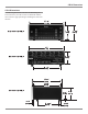
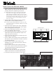
Figure 1