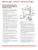
IMPORTANT SAFETY INSTRUCTIONS THESE INSTRUCTIONS ARE TO PROTECT YOU AND THE MclNTOSH INSTRUMENT. BE SURE TO FAMILIARIZE YOURSELF WITH THEM. 1. Read all instructions - Read the safety and operating instructions before operating the instrument. 2. Retain Instructions - Retain the safety and operating instructions for future reference. 3. Heed warnings - Adhere to warnings and operating instructions. 4. Follow Instructions - Follow all operating and use instructions.
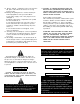
15. Nonuse Periods - Unplug the power cord from the AC power outlet when left unused for a long period of time. 16. Damage Requiring Service - Service must be performed by qualified service personnel when: A. The power supply cord or the plug has been damaged; or B. Objects have fallen, or liquid has been spilled into the instrument; or C. The instrument has been exposed to rain; or D. The instrument does not appear to operate normally or exhibits a marked change in performance; or E.
Contents INTRODUCTION FRONT PANEL HAND HELD REMOTE CONNECTIONS CONNECTIONS CONNECTIONS ACCESSORIES PERFORMANCE LIMITS BLOCK DIAGRAM 3 4 5 6, 7, 8, 9 10, 11, 12 13 14 15 16, 17 Your CR 7 and CR 8 Remote Control will give you many years of satisfactory performance. If you have any questions, please contact, CUSTOMER SERVICE Mclntosh Laboratory Inc. 2 Chambers Street Binghamton, New York 13903-9990 Phone: 607-723-3512 Take Advantage of 3 Years of Contract Service. . . Fill in the Application NOW.
The Mclntosh infrared Remote Control System provides unusual versatility with operating simplicity. It is a system which provides remote control in one listening area yet can be expanded to provide individual source selection with independent volume settings in up to five additional areas.
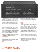
The touch-buttons on the black anodized aluminum front pane! of the CR7 control AC power to the local area, source selection, system mute and volume. In the upper right is an infrared sensor which receives the control data transmitted by the hand-held remote controller. In addition to the touch-buttons on the CR7, these functions and more, can be initiated by the hand-held remote controller.
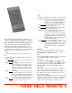
TUNER USING THE HAND HELD REMOTE CONTROLLER When The HR7 (hand held controller), is activated by pressing buttons on the keypad, it transmits a twelve bit code on an infrared carrier. When received by the infrared sensor, the transmitted data is decoded in the Remote Control Module. The infrared sensor has been designed for a broad reception angle so it is usually not necessary to point the hand-held controller directly at the sensor. POWER Turns the AC power on or off to the local area.
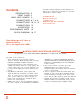
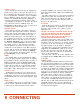
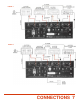
FIGURES 1 and 2 These illustrate the interconnection of equipment to provide remote control in one area, the main area. In this configuration the CR7 becomes the center of control for a preamplifier, a Mclntosh remote controllable tuner, a Mclntosh compact disc player and a power amplifier. The Mclntosh CR7 provides switching to interconnect and control the functions of these units. Each diagram, from Figure 3 on, illustrates the expansion of the basic system to additional areas.
FIGURE 1 FIGURE 2 CONNECTIONS 7
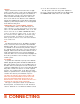
FIGURE 3 Figure 3 illustrates the interconnection of equipment to provide remote control in the main listening area and one remote listening area. The Mclntosh CR7 controls the system source and volume in the main area while the CR8 performs the same functions for the remote area. Because each additional remote area added to the system has its own power amplifier, power and performance are no! degraded in the main listening area.
FIGURE 3 CONNECTING 9
FIGURE 4 Figure 4 illustrates the interconnection of equipment to provide multiple area control capability for the system shown in Figure 3. By adding a Mclntosh R 606 MULTIPLE SENSOR ADAPTER up to six remote infrared sensors (Mclntosh R 607] can be added. Each sensor data is fed through the R 606 to the REMOTE AREA CONTROLLER.
FIGURE 5 Figure 5 illustrates the interconnection of equipment to provide a tuner as a source in the remote area independent of the tuner in the main area. The 25 pin cable provided to interconnect the CR8 with the CR7 is removed and replaced with a cable that has an additional 15 pin connector and two audio connectors with RCA plugs (Part # R617), The 15 pin connector is plugged into the REMOTE CONTROL socket on the tuner.
FIGURE 6 Figure 6 illustrates the use of an existing video distribution system to interconnect the remote sensors with a remote control module. By inserting a pair of Mclntosh R 615 VIDEO CABLE AND DC CONTROL ADAPTERS in the existing video distribution system, the video signals, the remote control data and the DC voltages to operate the remote sensors can all be conducted on the existing RG-59/U video distribution system without any interaction.
FIGURE 7 Figure 7 illustrates a system expanded to a main area and two independent control remote areas. One end of the cable with the 25 pin connectors is plugged into the 1st area remote CR8 socket labelled TO NEXT AREA CONTROLLER and the other end is plugged into the 2nd remote area CR8 AREA CONTROLLER INPUT socket. Up to five remote areas can be added to a CR7 main area each with independent source selection and volume adjustment. If wanted, additional tuners can be added as in Figure 5.
R 607 INFRARED REMOTE SENSOR R 607 REMOTE SENSOR designed to be installed in an electrical switch box for wall or celling installation. Ordinary video distribution cable (RG-59/U) connects the remote sensor to the main equipment infrared AREA SENSOR input. R 620 CABLE TO ACTIVATE SCAN (MR 80—MR 500—MAC 4200) Two connectors terminate the R 620 cable. One end has a 15 pin computer type connector and the other end a RCA type audio connector.
CR7 CR8 FREQUENCY RESPONSE FREQUENCY RESPONSE + 0, - 0.5 dB from 20 Hz to 20 KHz + 0, -0.5 dB from 20 Hz to 20 KHz RATED OUTPUT VOLTAGE 2.5V RATED OUTPUT VOLTAGE 2.5V SENSITIVITY AM input, 0.775V for 2.5V rated output TOTAL HARMONIC DISTORTION 0.
16 BLOCK DIAGRAM CR7 BLOCK DIAGRAM
BLOCK DIAGRAM 17 CR8 BLOCK DIAGRAM