Ceiling Loudspeaker System CS100 Installation Guide McIntosh Laboratory, Inc.
WARNING - TO REDUCE RISK OF FIRE OR ELECTRICAL SHOCK, DO NOT EXPOSE THIS EQUIPMENT TO RAIN OR MOISTURE. NO USER-SERVICEABLE PARTS INSIDE. REFER SERVICING TO QUALIFIED PERSONNEL. IMPORTANT SAFETY INSTRUCTIONS! PLEASE READ THEM BEFORE OPERATING THIS EQUIPMENT. General: 1. Read these instructions. 2. Keep these instructions. 3. Heed all warnings. 4. Follow all instructions. 5. Warning: To reduce risk of fire or electrical shock, do not expose this equipment to rain or moisture.
Table of Contents Safety Instructions ............................................................ 2 Thank You and Please Take a Moment............................. 2 Technical Assistance and Customer Service .................... 2 Table of Contents .............................................................. 3 Important Information ...................................................... 3 Performance Features ....................................................... 3 Dimensions ............................
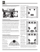
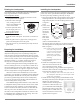
Dimensions The following dimensions can assist in determining the best location for the CS100 Loudspeaker System. 12-7/16" 31.60cm 10-3/8" 26.35cm 5-9/16" 14.13cm 6" 15.24cm 10-5/8" 26.99cm Installation Overview The CS100 Ceiling Loudspeaker System is designed to mount into the ceiling of a typical room. Before choosing the location in the ceiling for the CS100, it is important to read “Location in the Room” for the best possible performance.
Installation Painting the Loudspeaker Installing the Loudspeaker The CS100 Ceiling Loudspeaker System is primed and may be painted before or after installation. The Loudspeaker Frame: 1. Insert the supplied paint shield into the frame of the Loudspeaker. Refer to figure 5. 2. Paint the frame with light coats, to help prevent excessive paint buildup and “runs” on the frame. 3. After the paint has dried, use the finger pulls to remove the paint shield. Figure 5 The Loudspeaker Grille: 1.
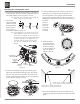
Installation Installing the Loudspeaker, con’t 6. Prepare the Loudspeaker hookup cables by carefully remove sufficient insulation from the cable ends and twist the strands together, refer to figures 9, 10 & 11. Note: If desired, the twisted ends can be tinned with solder to keep the strands together. 7. Connect the prepared hookup cables to the Full Range Terminals Figure 10 Figure 9 being careful to observe the correct polarities. Refer to figure 12.
W LOUDSPEAKER PRODUCTS FIVE YEAR LIMITED WARRANTY elcome to the family of McIntosh owners. This is the Warranty for your new McIntosh Loudspeaker Product (the “Speaker”). Your Speaker has been designed to give many years of trouble-free performance. Nonetheless, failures do sometimes occur even with equipment as well-built as McIntosh’s.
Specifications Specifications System Driver Complement One 8 inch DCDTM Copolymer Cone Woofer One 3-1/2 inch Neo Copolymer Cone Midrange One 1 inch VF® Aluminum Dome Tweeters Impedance 8 ohms Nominal Frequency Response 48Hz - 22kHz (±3dB) Sensitivity 89dB (2.83V/1m equivalent) Crossover Frequencies 400Hz 3,000Hz Power Handling 200 Watts Maximum General Specifications Operating Temperature 41 to 95oF 5 to 35oC Operating Humidity 30 to 85% McIntosh Laboratory, Inc.