C39 AUDIO/VIDEO CONTROL CENTER
C39 AUDIO/VIDEO CONTROL CENTER
1. 2. 3. 4. IMPORTANT SAFETY INSTRUCTIONS THESE INSTRUCTIONS ARE TO PROTECT YOU AND THE MclNTOSH INSTRUMENT. BE SURE TO FAMILIARIZE YOURSELF WITH THEM Read all instructions - Read the safety and operating instructions before operating the instrument. Retain Instructions - Retain the safety and operating instructions for future reference. Heed warnings - Adhere to warnings and operating instructions. Follow Instructions - Follow all operating and use instructions.
Your decision to own this piece of Mcintosh Stereo Equipment ranks you at the very top among discriminating music listeners. You now have "The Best". The Mcintosh dedication to "Quality", is assurance that you will receive thousands of hours of musical enjoyment from THANK YOU this unit. Please take a short time to read the information in this manual. We want you to be as familiar as possible with all the features and functions of your new piece of Mcintosh.
TAKE ADVANTAGE OF 3 YEARS OF CONTRACT SERVICE. . . FILL IN THE APPLICATION NOW. Your C39 Audio/Video Control Center will give you many years of satisfactory performance. If you have any questions, please contact, Mcintosh Laboratory Inc. 2 Chambers Street Binghamton, New York 13903-2699 Phone: 607-723-3512 An application for A THREE YEAR SERVICE CONTRACT is included with this manual. MclNTOSH THREE YEAR SERVICE CONTRACT The terms of the contract are: 1.
Mcintosh Laboratory has earned a world wide reputation for the technical superiority of its contributions to high quality sound reproduction. The advanced level of Mcintosh product innovations has integrity proven by time. The legendary reliability of Mcintosh products is a matter of record since 1949. The "Classic Mcintosh" design is acknowledged as the most outstanding in the audio industry. Mcintosh products are designed to be maximum "User Friendly". Anyone can enjoy using them.
INTRODUCTION tional audio program sources. A pair of low level inputs is included for a moving magnet phono cartridge. Six of the audio inputs are for the audio portion of an audio/video signal. Six matching standard and S Video inputs are also included. The C39 will simultaneously switch the six video and corresponding audio signals. The C39 uses digital Logic integrated circuits to drive Electromagnetic Switches for all input, output and operating functions.
All movies produced by major film companies have Dolby Stereo soundtracks. When they reach you via home video sources, the Dolby Surround encoding remains intact. Dolby Pro Logic relies on the same decoding technology as the professional cinema processors to decode the movie sound tracks that are found on video. The decoding process results in four separate sound tracks which are Left Front, Center, Right Front, and Surround.
HOME THEATER AUDIO CHANNEL CONFIGURATION WITH DOLBY PRO LOGIC™ AND HOME THX AUDIO There are specific Home THX Audio requirements for surround sound level calibration. This information is included in the manual section "MclNTOSH HOME THEATER SURROUND SOUND VOLUME LEVEL CALIBRATION". SUBWOOFER Home THX Audio specifications require a subwoofer to be used in a home theater system. A subwoofer loudspeaker is designed to reproduce only the lowest audio frequencies, which are essentially non-directional.
All audio or video tape recording must be setup manually in Area "A". Prior to a recording session, always press the REC (Record) LOCK pushbutton to disable all remote sensors or keypads to avoid accidental recording disruption. C. MODE (Selects the operating configuration) MONO: All left and right channel signals are combined for Mono operation and fed to the LEFT FRONT, RIGHT FRONT, Balanced, Unbalanced and the corresponding 6 CHANNEL connector outputs.
FRONT PANEL CONTROLS, SWITCHES AND PUSHBUTTONS CINEMA 2, H O M E THX AUDIO: TO REPRODUCE DOLBY SURROUND, PRO LOGIC DECODED MOVIE SOUNDTRACKS WITH H O M E THX AUDIO ENHANCEMENT. The CINEMA 2 or Home THX Audio mode of operation is possible only when the optional Mcintosh THX-M Module has been installed in the C39. The four Dolby Pro Logic processed output signals are fed to the Home THX Audio circuits in the THX-M module for further processing and enhancement which produce the following six outputs.
The VCR1, VCR2, TAPE 1, TAPE 2 and Area " B " Outputs are not affected by the front panel VOLUME Control. G. LOUDNESS and BALANCE (Concentric Controls) BALANCE control, (large outer knob): Adjusts the volume of the Left and Right channels relative to each other. The BALANCE control affects only the LEFT FRONT, RIGHT FRONT Unbalanced, LEFT and RIGHT Balanced, Area "A" Outputs and the six channel connector. The BALANCE Control is effective in all five modes of operation.
FRONT PANEL CONTROLS, SWITCHES AND PUSHBUTTONS I. SURR LEVEL, SURRound LEVEL, (SUR CAL), UP ( ) or DOWN ( ) UP ( ) and DOWN ( ) pushbuttons adjust the volume level match of all six channels as described in the manual section "MclNTOSH HOME THEATER SURROUND SOUND VOLUME LEVEL CALIBRATION". J. SURR PROC (SURRound PROCessor) Press the SURR PROC pushbutton if you wish to remove all signal processing functions in HALL, CINEMA 1 or CINEMA 2 modes, and return to normal STEREO mode.
HALL MODE DELAY TIMES In the HALL operating mode, the time delays are slightly longer than the panel indications. Set the delay according to your personal preference. The shorter delay times simulate a smaller room, while the longer delays simulate a large room or concert hall. FRONT PANEL INDICATION ACTUAL TIME DELAY IN MILLISECONDS 12 FRONT PANEL CONTROLS, SWITCHES AND PUSHBUTTONS 16.4ms 16 32.8ms 20 (Recommended Setting) 49.2ms 24 65.1ms 28 81.9ms O.
C39 HAND HELD REMOTE CONTROLLER 2. Select Tuner station presets or relay operation on the HC-1 Home Controller. First press the HOME pushbutton (4) and then the desired pushbuttons 0 through 9 (2) within five seconds to activate the relays on the HC-1. The number pushbuttons also function with the RCT-1 Remote Control Translator, when it is programmed to allow the C39 to remotely control other brand products. 3. Select CD Player, CD Changer or tape recorder functions.
10. Press MUTE to mute the audio signals separately in either Area "A" or " B " . Area "A" muting is in dicated by a Red LED above the MUTE pushbutton that blinks on and off. To unmute Area "A", press MUTE a second time, press an UP ( ) or DOWN ( ) VOLUME pushbutton or turn the front panel VOLUME control. 11. SP (Surround Processor pushbutton switches Area "A" surround signal processing func- C39 HAND HELD REMOTE CONTROLLER tions IN or OUT, in HALL, CINEMA 1 or CINEMA 2 modes.
THE REAR PANEL AND HOW TO MAKE CONNECTIONS THE CHANNEL ALLOCATION IS AS FOLLOWS: CHANNEL 1 Center Front CHANNEL 2 Left Surround CHANNEL 3 Left Front CHANNEL 4 Right Front CHANNEL 5 Subwoofer CHANNEL 6 Right Surround 1. SUR (SURround) Connect a pair of cables from the SURround AUDIO OUTPUT jacks to the inputs of the power amplifier channels which will feed left and right surround sound loudspeakers. 2.
IN BYPASS MODE, FOR THE PROGRAM SIGNALS TO BE FED TO THE VCR, TAPE OR AREA "B" AUDIO OUTPUTS. 8. VCR1, 2 and V-AUX (Auxiliary) Connect cables from the Audio Outputs of VCR units or other similar Audio/Video accessories to these three AUDIO INPUTS. 9. LV (Laser Video) Connect a pair of cables from a Laser Video Disc player Audio Outputs to the LV AUDIO INPUTS. 10. TV Connect a pair of cables from the Audio Outputs of a TV set, TV Monitor or TV Tuner to the TV INPUTS. 11.
THE REAR PANEL AND HOW TO MAKE CONNECTIONS BALANCED jacks are present whenever the C39 Area "A" is on and operating, and are the same signals as at the Unbalanced Left Front and Right Front Outputs. Using balanced connectors and cables can reduce noise and interference by as much as 40dB. This extra noise reduction can be a significant improvement, especially if the cables are quite long.
The interconnect cable from the C39 POWER CONTROL jack to the MC7106 POWER CONTROL IN jack uses single conductor shielded wire with 1/8" mini phone plugs. Connections are to the sleeve and tip of the plug. 22. SURROUND CALIBRATE, (AUTO, MANual) Set this switch to the AUTOMATIC position for the built-in noise generator to automatically switch its signal to each of the six channels in sequence, for surround volume level calibration and trim procedure required for HALL, CINEMA 1 and CINEMA 2 operating modes.
THE REAR PANEL AND HOW TO MAKE CONNECTIONS corresponding audio signals will be switched simultaneously. VCR1: Connect cables from either the S or Standard VCR1 Video Output to the video inputs of a VCR. VCR2: Connect cables from either the S or Standard VCR2 Video Output to the video inputs of a second VCR. Use either S or Standard Video connectors for all inputs and outputs. Do not mix connector types. 27.
tions in Area " B " . Area " B " must have its own dedicated power amplifier and speakers. All coaxial connections use either RG59U or RG6 coaxial cable. Up to four Keypads or Sensors can be connected in parallel on each coaxial cable. 32. TUNER CONTROL Connect a Mcintosh Model W102 Tuner Control cable from the TUNER CONTROL connec- THE REAR PANEL AND HOW TO MAKE CONNECTIONS tor to a connector on a compatible Mcintosh tuner.
HOW TO SET UP YOUR MclNTOSH HOME THEATER configurations. You may find it convenient to take advantage of the technical knowledge and experience of your Mcintosh dealer to assist you in the setup procedure. Reproducing Dolby Surround movie soundtracks with Dolby Pro Logic decoding requires a specific selection and location of loudspeakers. If you are using the optional THX-M module in your C39 for Home THX Audio processing, the requirements are even more specific.
Home THX Cinema Directivity (as seen from the side) HOME THEATER LAYOUT The front speakers must be aimed directly at the listening area. This is due to their vertical directivity, which greatly enhances dialog intelligibility and image localization. Home THX Cinema Directivity (as seen from above) The Surround speakers must be even with and above the listener. This ensures that the audience hears only ambient, reflected sound from the Surround channels, and can never localize them independently.
HOME THEATER HOOK-UP VCR1 LV (LASER DISC) VCR 2 TUNER TELEVISION C39 OR MX130 MC7106 MclNTOSH HT-1 LEFT FRONT MclNTOSH HT-1 CENTER MclNTOSH HT-1 RIGHT FRONT MCINTOSH HT-2 SUB WOOFER MclNTOSH HT-3 LEFT SURROUND 24 MclNTOSH HT-3 RIGHT SURROUND TO CR10
The Mcintosh C39 has a convenient built-in Noise generator to allow trimming volume levels for each of the six channels. This process is described as Surround Sound Calibration. These selected volume levels are then retained in the C39 Control Center memory. MANUAL CHANNEL CYCLING FOR CINEMA 1 DOLBY PRO LOGIC SURROUND SOUND LEVEL CALIBRATION 1. Set the MODE Switch to CINEMA 1. 2. Set the C39 VOLUME control to a level between 3 0 % ± 10%. 3. Set the rear panel SURROUND CALIBRATE Switch to MANUAL.
MclNTOSH HOME THEATER SURROUND SOUND VOLUME LEVEL CALIBRATION continue to the next channel. Adjust the levels of each of the six individual channels with the front panel UP ( ) or DOWN ( ) SURR LEVEL, (SUR CAL) pushbuttons until you achieve the level match you prefer in the listening area. It is recommended that all channel volume levels be as close to the same as possible.
Accurate THX Volume calibration requires the use of a calibrated sound level meter positioned in the listening area at seated ear height. The meter is necessary to set the acoustic sound levels from each loudspeaker to 75dB as specified by the Home THX Audio standards. MANUAL C H A N N E L CYCLING FOR CINEMA 2 HOME THX AUDIO SURROUND LEVEL CALIBRATION 1. Set the C39 LISTEN Selector switch to the LV (Laser Video Disc Player) position. 2. Set the MODE Switch to CINEMA 2. 3.
MCINTOSH HOME THEATER SURROUND SOUND VOLUME LEVEL CALIBRATION SURROUND CALIBRATION LEVEL TRIM NUMBERS LEFT FRONT: CENTER: RIGHT FRONT: RIGHT SUR: LEFT SUR: SUBWOOFER: LEFT FRONT: CENTER: RIGHT FRONT: RIGHT SUR: LEFT SUR: SUBWOOFER: AUTOMATIC CHANNEL CYCLING FOR CINEMA 2 HOME THX AUDIO SURROUND LEVEL CALIBRATION The Automatic mode of Home THX Audio surround level calibration is not recommended since there may not be adequate time to get valid readings from the Sound Level Meter.
FREQUENCY RESPONSE SPECIFICATIONS MONO and STEREO MODES LEFT, CENTER and RIGHT FRONT channels +0, - 0 . 5 d B from 20Hz to 20,000Hz HALL MODE LEFT, CENTER and RIGHT FRONT channels, +0, - 0 . 5 d B from 20Hz to 20,000Hz. LEFT and RIGHT SURROUND channels, +0, - 3 d B from 100Hz to 7000Hz. DOLBY PRO-LOGIC MODE LEFT, CENTER and RIGHT FRONT channels, ±0.5dB from 30Hz to 16,000Hz.
SPECIFICATIONS SIGNAL TO NOISE RATIO A-WEIGHTED MONO, STEREO and HALL MODES LEFT, CENTER and RIGHT FRONT channels, PHONO: 90dB below 10mV input, (84dDB IHF). HIGH LEVEL: 100dB below rated output (95dB IHF). DOLBY PRO-LOGIC and THX MODES All outputs greater than 70dB below reference level. MAXIMUM INPUT SIGNAL PHONO: 60mV. HIGH LEVEL: 5V MONO and STEREO, 2.1V HALL, DOLBY PRO-LOGIC and THX. INPUT IMPEDANCE PHONO: 47K ohms and 65pF capacitance. HIGH LEVEL: 22K ohms.
1/4" 6mm CUSTOM INSTALLATION DRAWING OUTLINE OF FRONT PANEL EDGE OF CUTOUT END CAPS 7-1/16" 179.8mm PANEL HEIGHT 7" 177.8mm 6-9/16" 166.7mm 7/32" 5.3mm 17-1/16" 433.4mm 3/16" 5.
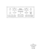
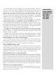
The letters and numbers correspond to the paragraphs on pages 8 through 2 1 .
04013600