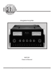
Integrated Amplifier MA7000 Owner’s Manual McIntosh Laboratory, Inc.
The lightning flash with arrowhead, within an equilateral triangle, is intended to alert the user to the presence of uninsulated “dangerous voltage” within the product’s enclosure that may be of sufficient magnitude to constitute a risk of electric shock to persons. WARNING - TO REDUCE RISK OF FIRE OR ELECTRICAL SHOCK, DO NOT EXPOSE THIS EQUIPMENT TO RAIN OR MOISTURE. IMPORTANT SAFETY INSTRUCTIONS! PLEASE READ THEM BEFORE OPERATING THIS EQUIPMENT. 1. Read these instructions. 2. Keep these instructions. 3.
Thank You Table of Contents Your decision to own this McIntosh MA7000 Integrated Amplifier ranks you at the very top among discriminating music listeners. You now have “The Best.” The McIntosh dedication to “Quality,” is assurance that you will receive many years of musical enjoyment from this unit. Please take a short time to read the information in this manual. We want you to be as familiar as possible with all the features and functions of your new McIntosh. Safety Instructions .......................
Connector Information, Introduction and Performance Features Connector and Cable Information Performance Features XLR Connectors Below is the Pin configuration for the XLR Balanced Input and Output Connectors on the MA7000. Refer to the diagram for connection: PIN 1: Shield/Ground PIN 2: + Output PIN 3: - Output • Power Output with Patented Autoformer The MA7000 consists of a 250 watts per channel stereo Power Amplifier with less than 0.005% distortion.
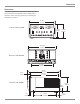
Dimensions Dimensions The following dimensions can assist in determining the best location for your MA7000. There is additional information on the next page pertaining to installing the MA7000 into cabinets. 17-1/2" �� �� � Front View of the MA7000 � 44.45cm 8-13/16" 22.38cm 9-7/16" 23.97cm 16-13/16" 42.70cm Rear View of the MA7000 11-1/2" 29.21cm 19-3/4" 50.17cm 2-1/4" 16-7/16" 5.72cm 41.75cm Side View of the MA7000 8-1/4" 3/16" 0.48cm 7/8" 2.22cm 12-3/4" 32.39cm 20.96cm 1-1/4" 3.
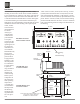
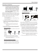
Installation Installation 6 � �� �� � Allow at least 6 inches (15.24cm) above the top, 2 inches The MA7000 can be placed upright on a table or shelf, (5.08cm) below the bottom and 1 inch (2.54cm) on each standing on its four feet. It also can be custom installed in side of the Integrated Amplifier, so that airflow is not oba piece of furniture or cabinet of your choice. The four feet structed. Allow 20 inches (50.8cm) depth behind the front may be removed from the bottom of the MA7000 when it panel.
Rear Panel Connections Connect the MA7000 power cord to a live AC outlet.
Connecting Components The MA7000 has the ability to automatically switch power On/Off to McIntosh Source Components via the Power Control connections. The Data Port Connections allow for the remote operation of basic functions using the MA7000 Remote Control. With an external sensor connected to the MA7000, remote control operation of the system is possible from another room and/or when the MA7000 is located in a cabinet with the doors closed.
How to Connect Connecting Loudspeakers Caution: The supplied AC Power Cord should not be connected to the Rear Panel of the MA7000 Amplifier until after the Loudspeaker Connections have been made. Failure to observe this could result in Electric Shock. For additional instruction on making Loudspeaker Connections contact your McIntosh Dealer or McIntosh Technical Support.
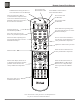
Remote Control Push-Buttons LED illuminates during the time a remote command is sent to the MA7000 Press to Power the MA7000 ON or OFF Press MODE to switch between Stereo and Mono Modes Turns AC Power ON or OFF to certain McIntosh Components when connected via the Data Port and any McIntosh Components connected to the ACC Power Control Jack Press to Power ON the MA7000 Switches OFF the entire MA7000 System Selects FM Tuner Operating Functions and Track Selection on certain McIntosh CD Players Use to
How to use the Remote Control How to use the Remote Control The supplied Remote Control is capable of directly controlling the functions of contemporary McIntosh Source Components connected to the MA7000 via the Data Ports. Input Source Selection Press the appropriate Source Push-button to select the desired program source. Mute Press the MUTE Push-button to mute the audio in all outputs except the REC OUTPUT. The MUTE LED above the push-button will flash on and off to indicate that Mute is active.
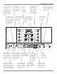
Front Panel Displays, Controls, Push-buttons and Jack LED indicates when the Left Channel Amplifier POWER GUARD circuit activates Meter indicates the Right Channel Output of the amplifier Equalizer Controls provide 12dB of boost or cut at the center frequencies indicated above each control The LEDs above the push-buttons indicate the current source selected.
How to Operate the MA7000 How to Operate the MA7000 Power On The Red LED above the STANDBY/ON Push-button lights to indicate the MA7000 is in Standby mode. To Switch ON the MA7000, press the STANDBY/ON Push-button on the Front Panel or the Power Push-button on the Remote Control. The MUTE LED will light for approximately two seconds after turn on. Refer to page 12 and figure 7. Note: For an explanation of the Remote Control Push-button functions, refer to pages 10 and 11.
How to Operate the MA7000, con’t How to Operate the MA7000, con’t Using a Separate Power Amplifier There are two different ways to use a separate power amplifier with a MA7000. The first way is to use the separate amplifier instead of the MA7000 built-in Power Amplifier. Connect the Loudspeakers to the separate power amplifier and remove the McIntosh Jumpers that are located between the OUTPUTS 1 Jacks and the POWER AMP INput Jacks. Refer to figure 8.
Technical Description Technical Description McIntosh Laboratory, the company who introduced the world’s first amplifier that could be called “High Fidelity”, has done it again. The McIntosh engineering staff has created a power amplifier without compromise, using the most advanced McIntosh circuit design concepts.
sealed with tiny leads protruding from either end. Refer to figure 10. These leads extend into the tube and overlap one another with a separation of a few thousandths of an inch. The leads are made from a ferrous material that Figure 10 is influenced by a magnetic field. They are first plated with gold as a base material, then with rhodium and finally ruthenium. Ruthenium is the best contact material known. The glass assembly is then placed in the center of a multilayer coil of copper wire.
Technical Description, con’t Autoformers All solid state power amplifier output circuits work best into what is called an optimum load. This optimum load may vary considerably from what a loudspeaker requires. In the case of more than one loudspeaker connected in parallel, the load to the power amplifier may drop to two ohms or even less.
Specifications Specifications Power Output 250 watts is the minimum sine wave continuous average power output per channel, both channels operating Output Load Impedance 2, 4 or 8 ohms Rated Power Band 20Hz to 20,000Hz Total Harmonic Distortion 0.005% maximum with both channels operating from 250 milliwatts to rated power, 20Hz to 20,000Hz Dynamic Headroom 2.0dB Frequency Response +0, -0.5dB from 20Hz to 20,000Hz +0, -3dB from 10Hz to 100,000Hz Preamplifier Main Output (for rated input) 2.
Packing Instructions Packing Instructions In the event it is necessary to repack the equipment for shipment, the equipment must be packed exactly as shown below. It is very important that the four plastic feet are attached to the bottom of the equipment. Four 1/4 - 20x2-1/4 inch screws and washers must be used to fasten the unit securely to the bottom pad and wood skid. This will ensure the proper equipment location on the bottom pad. Failure to do this will result in shipping damage.
McIntosh Laboratory, Inc. 2 Chambers Street Binghamton, NY 13903 The continuous improvement of its products is the policy of McIntosh Laboratory Incorporated who reserve the right to improve design without notice. Printed in the U.S.A. McIntosh Part No.