
Owner's Manual
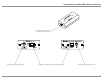
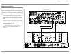
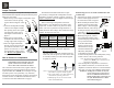
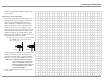
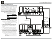
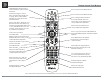
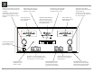
Table Of Contents
- Owners Manual
- Rear Panel Connections
- Tuner Module Installation and Connecting Antennas
- Connection Diagrams
- Remote Control Owners Manual
- Preferred Settings for Use with a PC
- Spec Sheet
- Warranty

12
Connecting Components
The MA/MAC6700 has the ability to automatically
switch power On/Off to McIntosh Source Compo-
QHQWVYLDWKH3RZHU&RQWURO7ULJJHUFRQQHFWLRQV
The Data Port Connections allow for the remote
operation of basic functions using the MA/MAC6700
Remote Control. With an external sensor connected
to the MA/MAC6700, remote control operation of the
system is possible from another room and/or when the
MA/MAC6700 is located in a cabinet with the doors
closed.
If the optional Tuner Module is to be installed into
the MA6700 (the MAC6700 Tuner Module is factory
LQVWDOOHGSOHDVHSURFHHGDWWKLVWLPHWRWKHLQVWDOOD-
tion procedure located on the separate folded sheet
“Mc1B”.
The connection instructions below, together
with the MA/MAC6700 Input and Output Connec-
tion Diagrams located on the separate folded sheet
“Mc2A/2B”, are an example of a typical audio
system. Your system may vary from this, however the
actual components would be connected in a similar
manner. For additional information refer to “Connec-
tor and Cable Information” on page 5.
Note: Source components may be connected to the
MA/MAC6700 Balanced Inputs or Digital Inputs
instead of Unbalanced Inputs. Refer to Setup
“Reassigning Inputs” to activate them on page
22.
Power Control Connections:
1. Connect a Control Cable from the MA/MAC6700
3:5&75/3RZHU&RQWURO0$,1-DFNWRWKH
Power Control In on the Turntable.
2. Connect a Control Cable from the McIntosh Turn-
table Power Control Out Jack to the Audio/Video
Player Power Control In Jack.
3. Connect a Control Cable from the Audio/Video
Player Power Control Out Jack to the SACD/CD
Player Power Control In Jack.
4. Optionally connect a Control Cable from the MA/
0$&3:5&75/3RZHU&RQWURO75,*
7ULJJHU-DFNWRWKH3RZHU$PSOLILHU6HFRQG-
DU\5RRP3RZHU&RQWURO,Q-DFN
Note: The default setting for the TRIG 2 Jack is
“MAIN”. Refer to Setup “Power Control Trig-
gers 1 and 2” on page 24 to change TRIG 2 set-
ting to “OUTPUT 2”.
5. Connect any additional McIntosh Components in a
similar manner, as outlined in steps 1 thru 3.
Data Control Connections:
6. Connect a Control Cable from the MA/MAC6700
CD DATA PORT Jack to the SACD/CD Player
Data In Jack.
7. Connect a Control Cable from the MA/MAC6700
DVD DATA PORT Jack to the Audio/Video
Player Data In Jack.
8. Connect any additional McIntosh Components in
a similar manner, as outlined in steps 6 thru 7.
Sensor Connection:
9. Optionally, connect the cable with stereo mini
plug coming from the compatible External Sensor
WRWKH(;7&75/([WHUQDO&RQWURO,5,1-DFN
on the MA/MAC6700. Refer to page 5 “General
Information, note 7” for additional information.
Audio Connections:
10. Connect Balanced Cables from the MA/MAC6700
%$/%DODQFHG/5&RQQHFWRUVWRWKH6$&'
CD Player Fixed Audio Output Balanced Connec-
tors.
11. Connect Audio Cables from the MA/MAC6700
DVD INPUT Jacks to the Audio/Video Player
Output Jacks.
12. Connect the Audio Cables coming from the Turn-
table to the MA/MAC6700 MC (for a Moving Coil
&DUWULGJHRU00IRUD0RYLQJ0DJQHW&DUWLGJH
INPUT Jacks.
13. Optionally, connect Audio Cables from the MA/
MAC6700 OUTPUT 2 Jacks to the Power Ampli-
ILHU6HFRQGDU\,QSXW-DFNV
14. Connect any additional Components in a similar
manner, as outlined in steps 10 thru 13.
Optional Digital Audio Connections:
15. Connect a Coaxial Cable from the MA/MAC6700
',*'LJLWDO'LJLWDO$XGLR,QSXW-DFNWRWKH
Digital Out Coaxial Jack on the Audio/Video
Player.
16. Connect an Optical Cable from the MA/MAC6700
',*'LJLWDO'LJLWDO$XGLR,QSXWFRQQHFWRUWR
the Digital Audio Out Optical Connector on the
SACD/CD Player.
Optional USB Connection:
&RQQHFWD86%FDEOHZLWKW\SH$WRW\SH%FRQ-
nectors from the MA/MAC6700 USB D/A Digital
Audio Input to an available USB connector.
*URXQG&RQQHFWLRQV
18. Connect the Ground Cable coming from the Turn-
table to the MA/MAC6700 GND Binding Post.
Notes: 1. If the MA/MAC6700 is part of a Home Theater
System, proceed to “PassThru” connection on
page 13.
2. When the MA/MAC6700 will used together
with a separate Power Amplifier for Bi-Am-
plification of a Loudspeaker System, proceed
page 16.
Connecting Components