
Owner's Manual
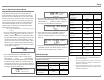
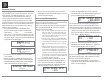
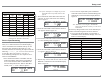
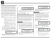

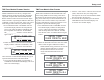
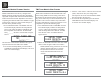
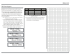
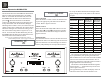
Table Of Contents
- Owners Manual
- Rear Panel Connections
- Tuner Module Installation and Connecting Antennas
- Connection Diagrams
- Remote Control Owners Manual
- Preferred Settings for Use with a PC
- Spec Sheet
- Warranty

22
The MA/MAC6700 functionality is controlled by
internal software that is know as Firmware. The MA/
MAC6700 has two different Firmwares, one is the
“System Firmware” (responsible for the basic op-
HUDWLRQRIWKH0$0$&DQGWKHRWKHUNQRZQ
as USB Audio Firmware (responsible for the “USB
Connection and Conversion” of a Digital Audio Signal
IURPWKH&RPSXWHU7KH9HUVLRQRIWKH)LUPZDUHVLQ
the MA/MAC6700 can be identified at any time by
utilizing the Setup Mode.
1. Press and hold the INPUT CONTROL until
the Front Panel Display indicates “MA6700 (or
0$&9BBB61BBBBBBB´7KHQXPEHU
after the “V” is the firmware version and the num-
ber after the “S/N” is the serial number of the unit
RUKLJKHU5HIHUWRILJXUH$IRUWKH0$DQG
Figure 2B for the MAC6700.
2. The number after the character “V” is the Firm-
ware number.
3. Rotate the INPUT CONTROL Clockwise until
the Front Panel Display indicates “McIntosh USB
$8',20$RU0$&9RUKLJKHU
USB Audio Firmware”. Refer to figure 3.
2. Rotate the VOLUME Control until “SETUP:
SOURCE INPUT, CD :BALANCED” appears on
the Front Panel Display. Refer to figure 5.
The second example will illustrate reassigning the
&',QSXWFRQQHFWHGWRD6$&'&'3OD\HUIURP
&',QSXW5&$-DFNVWRWKH',*LWDO2SWLFDO,QSXW
3. Press the VOLUME Control and the CD Input will
change to the CD2 INPUT. The Front Panel Dis-
play will now indicate “SETUP: SOURCE INPUT,
CD2 :RCA” . Refer to figure 6.
4. Rotate the VOLUME Control until “SETUP:
SOURCE INPUT, CD2 :DIGITAL 1” appears on
the Front Panel Display. Refer to figure 7.
Record any changes made to the various inputs from
the default settings in the “Input and Power Control
Settings” chart for future reference.
5. To exit from the Setup Mode, press the INPUT
CONTROL and the Front Panel Display will revert
back to its normal display.
The MA/MAC6700 provides the ability to reassign
+LJK/HYHO,QSXWVQRQ3KRQRWRHLWKHUWKH%DODQFHG
Input or one of the two Digital Inputs.
In the first example, the CD Input will be reassigned
IURPWKHXQEDODQFHG&'5&$-DFNVWRWKH%$/-
$1&('&RQQHFWRUV;5/
Notes: 1. Any one of the Default Inputs may be swiched
Off. If any input is switched Off its name will
no longer appear on the Front Panel Display
when using the INPUT Control, nor is it acces-
sible with the Remote Control.
2. The Phono MC (Moving Coil) and MM (Mov-
ing Magnet) Input are designed for connection
of a turntable only and thus non-reassignable.
However, the Phono Inputs may be switched
Off.
3. Only one Input may be assigned at a time to
the Balanced or Digital (1 or 2) Connectors. If
an already assigned Balanced or Digital con-
nector is to be reassigned to a different Input,
the Input currently assigned to the connector
first needs to be changed. It can be temporarily
set to Off, RCA connector, available Balanced
or available Digital connector.
1. Press and hold the INPUT CONTROL until the
Front Panel Display indicates the Setup Mode is
active. Then rotate the INPUT CONTROL and
select the Setup Menu item “SETUP: SOURCE
INPUT, CD :RCA”. Refer to figure 4.
Figure 5
SETUP: SOURCE INPUT
CD : BALANCED
Figure 4
SETUP: SOURCE INPUT
CD : RCA
Figure 6
SETUP: SOURCE INPUT
CD2 : RCA
SETUP: SOURCE INPUT
CD2 : DIGITAL 1
Figure 7
Source Input Reassignment
Firmware Version
4. To exit from the Setup Mode, press the INPUT
CONTROL and the Front Panel Display will revert
back to its normal display.
Figure 2A
MA6700 V_.__
S/N: _______
Figure 2B
MAC6700 V_.__
S/N: _______
Figure 3
McIntosh USB Audio
V_.__