
User's Manual


13
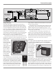
range of music conditions with the benefits of lower distor-
tion and cooler operation.
The MC303 can provide greater than 60 amperes peak
output current to drive uneven speaker loads. Some poor
speaker designs have input impedance that dip to 1 or 2
ohms at various frequencies and the MC303 has the output
current reserve to drive them.
The high efficiency circuit design of the MC303 con-
tributes to low operating temperatures. More than 2,100
square inches of heat sink area keep the MC303 operating
safely with convection cooling. No fans are needed. Preci-
sion metal film resistors and low dielectric absorption film
capacitors are used in all critical circuit locations.
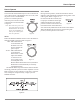
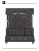
Autoformers
The output signal of the MC303 Power Amplifier Circuitry
is coupled to the Loudspeaker via the unique McIntosh
Output Autoformer. Refer to figure 15. The unequaled ex-
pertise of McIn-
tosh in the design
and manufactur-
ing of autoform-
ers is legendary
in the high fidel-
ity industry.
All solid state
power amplifier
output circuits
work best into
what is called
an optimum load. This optimum load may vary consider-
ably from what a loudspeaker requires. In the case of more
than one Loudspeaker connected in parallel, the load to
the power amplifier may drop to two ohms or even less. A
power amplifier connected to a load that is lower than opti-
mum, causes more output current to flow, which results in
extra heat being generated in the power output stage. This
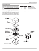
Design Philosophy
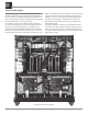
The design philosophy incorporated in the MC303 in-
volved several different techniques, all based on sound
scientific logic. Refer to figure 12. Every stage of voltage
or current amplification must be as linear as possible prior
to the use of negative feedback. McIntosh engineers know
how to properly design negative feedback circuits so they
contribute to the extremely low distortion performance
expected from a McIntosh amplifier. The typical McIntosh
owner would never accept the approximately 100 times
higher distortion of many non-feedback designs.
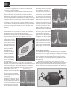
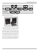
All transistors are selected to have nearly constant cur-
rent gain over the entire current range they must cover. The
12 Power Transistors used in each channel of the MC303
Power Output
Circuitry, have
matched uniform
current gain, high
current band-
width product and
a large active re-
gion safe operat-
ing area. Refer to
figure 13. These
Power Transistors
are the very latest
in semiconduc-
tor technology
and incorporate
a new design known as ThermalTrak™. Refer
to figure 14. This allows for the instantaneous
and accurate monitoring of the Power Transis-
tor Temperature. The MC303 Power Output
Circuitry has a specially designed bias circuit
to take full advantage of the ThermalTrak™
Power Transistors and thus precisely controls
the power amplifier operation over a wide
Technical Description
Figure 14
Figure 12
com
BALANCED
AMP
POSITIVE
SENTRY
MONITOR
NEGATIVE
SENTRY
MONITOR
THERMAL
TRAK
DC BIAS
Power Amplifier
Block Diagram
(one channel shown)
Figure 13
Figure 15