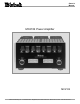
Owners Manual MC2102 Power Amplifier MC2102 McIntosh Laboratory, Inc.
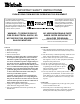
IMPORTANT SAFETY INSTRUCTIONS! PLEASE READ THEM BEFORE OPERATING THIS EQUIPMENT. The lightning flash with arrowhead, within an equilateral triangle, is intended to alert the user to the presence of uninsulated dangerous voltage within the products enclosure that may be of sufficient magnitude to constitute a risk of electric shock to persons. WARNING - TO REDUCE RISK OF FIRE OR ELECTRICAL SHOCK, DO NOT EXPOSE THIS EQUIPMENT TO RAIN OR MOISTURE. General: 1. Read these instructions. 2.
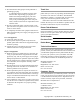
17. Do not defeat the safety purpose of the polarized or grounding-type plug. A polarized plug has two blades with one wider than the other. A grounding type plug has two blades and a third grounding prong. The wide blade or the third prong are provided for your safety. If the provided plug does not fit into your outlet, consult an electrician for replacement of the obsolete outlet. 18.
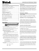
Introduction and Performance Features Table of Contents Introduction Safety Instructions ............................................................ 2 Thank You and Please Take a Moment............................. 3 Technical Assistance and Customer Service .................... 3 Table of Contents and General Notes ............................... 4 Introduction ...................................................................... 4 Performance Features ..................................................
MC2102 Dimensions MC2102 Dimensions The following dimensions can assist in determining the best location for your MC2102. There is additional information on page 8 pertaining to installing the MC2102 into cabinets. 17-3/4" 45.09cm 8-7/8" 22.54cm Front View of the MC2102 10-1/8" 25.72cm 17" 43.18cm Rear View of the MC2102 13-11/16" 34.77cm 16-3/4" 42.55cm 16" 40.64cm Side View of the MC2102 8-1/8" 20.64cm 9-3/4" 24.77cm 3/4" 1.91cm 12-3/4" 1-3/16" 32.39cm 3.
Installation of Tubes and Tube Cover Caution: To prevent electrical shock make sure that the AC POWER CORD IS NOT CONNECTED TO THE MC2102 when inserting or removing Tubes, as there are hazardous voltages present at the pins of the Tube sockets. Your MC2102 has gone through an extensive series of performance tests during the manufacturing process. The MC2102 is supplied with the actual Tubes that were used to test and confirm the performance of this amplifier.
Installation of Tubes, Tube Cover, Location and Ventilation There are two different types of Small Signal Tubes (12AX7A and 12AT7) used in each channel. Tube type can be found on the outside of the Tube. The MC2102 will not function if they are inserted into the wrong socket. Small Signal Tubes: 1. Locate a 12AX7A Tube. 2. On the top left side of the amplifier, locate the Tube Socket that has the nomenclature V1L 12AX7A next to it on the chassis. Refer to figure 4 and 5. 3.
Installation in a Custom Cabinet 1 inch (2.54cm) in front of the mounting panel for knob The MC2102 can be placed upright on a table or shelf, standing on its four feet. It also can be custom installed in a clearance. Be sure to cut out a ventilation hole in the mounting shelf according to the dimensions in the drawing. piece of furniture or cabinet of your choice. The four feet may be removed from the bottom of the MC2102 17-1/4" when it is custom installed 43.82cm as outlined below.
MC2102 Top Rear Panel Connections and Switchs Main Fuse holder, refer to information on the back panel of your MC2102 to determine the correct fuse size and rating Connect the MC2102 power cord to a live AC outlet.
How to Connect for Stereo Caution: The supplied AC Power Cord should not be connected to the Rear Panel of the MC2102 Amplifier until after the Loudspeaker Connections have been made and the supplied protective Terminal Connections Cover has been installed. Failure to observe this could result in Electric Shock. 1. For Remote Power Control, connect a power control cable from the Control Center or Preamplifier Power Control Out to the MC2102 Power Control In. 2.
How to Connect for Stereo McIntosh C200C Controller McIntosh C200P Preamplifier To AC Outlet Right Loudspeaker 4 ohm Left Loudspeaker 4 ohm 11
How to Connect for Mono Parallel Caution: The supplied AC Power Cord should not be connected to the Rear Panel of the MC2102 Amplifier until after the Loudspeaker Connections have been made and the supplied protective Terminal Connections Cover has been installed. Failure to observe this could result in Electric Shock. 1. For Remote Power Control, connect a power control cable from the Control Center or Preamplifier Power Control Out to the MC2102 Power Control In. 2.
How to Connect for Mono Parallel McIntosh C200C Controller McIntosh C200P Preamplifier To AC Outlet Jumper Cables 0RQR 3DUDOOHO +RRNXS &RQQHFWLRQV 4 ohm Loudspeaker 6S H DNH U ,PS HG D QFH R KP RKP R KP 6S HD NHU 1H JD WLYH & RQQH FWL RQ / H IW D QG 5 LJKW & R P & R QQH F W LR Q / H IW D QG 5 LJKW & R P & R QQH F W LR Q / H IW D QG 5 LJKW & R P & R QQH F W LR Q 6SH D NHU 3 R VL WL YH & RQQH FWL R Q / H IW D QG 5 LJKW 2 XW S XW R KP & R QQH F W LR Q / H
How to Connect for Mono Bridge Caution: The supplied AC Power Cord should not be connected to the Rear Panel of the MC2102 Amplifier until after the Loudspeaker Connections have been made and the supplied protective Terminal Connections Cover has been installed. Failure to observe this could result in Electric Shock. 1. For Remote Power Control, connect a power control cable from the Control Center or Preamplifier Power Control Out to the MC2102 Power Control In. 2.
How to Connect for Mono Bridge McIntosh C200C Controller McIntosh C200P Preamplifier To AC Outlet 4 ohm Loudspeaker 0RQR %ULGJH +RRNXS &RQQHFWLRQV 6S H DNH U ,PS HG D QFH R KP RKP RKP 6S HD NHU 1H JD WLYH & RQQH FWL RQ 6SH D NHU 3 R VL WL YH & RQQH FWL R Q /H IW 2 XWS XW R KP 5 LJKW 2 XWS XW R KP & R QQH F WLR Q & R QQH F W LR Q /H IW 2 XWS XW R KP 5 LJKW 2 XWS XW R KP & R QQH F WLR Q & R QQH F W LR Q /H IW 2 XWS XW R KP 5 LJKW 2 XWS X
Front Panel Displays and Controls METER indicates the Left Channel Power Output of the amplifier METER indicates the Right Channel Power Output of the amplifier Remote On Indicator lights when the amplifier is in the Remote Turn-On Mode METER Switch selects the display modes of the Power Output Meters 16 POWER Switch Turns AC Power Off, Remote or On
How to Operate the MC2102 How to Operate the MC2102 Power On To have the MC2102 automatically turn On or Off when a McIntosh Control Center turns On or Off, rotate the power switch to the REMOTE Position. For manual operation, rotate the power switch to the ON or OFF Position as desired. Refer to figure 15. Mode Switchs The STEREO/PARALLEL/BRIDGE MONO Mode Switch, which is located on the Top Rear Panel of the MC2102, allows you to select either STEREO, MONO PARALLEL or MONO BRIDGE Modes of Operation.
Specifications Specifications Power Output Stereo Minimum sine wave continuous average power output per channel, all channels operating is: 100 watts into 2 ohm load 100 watts into 4 ohm load 100 watts into 8 ohm load Power Output Mono Parallel Minimum sine wave continuous average power output is: 200 watts into 1 ohm, 2 ohm or 4 ohm load Power Output Mono Bridge Minimum sine wave continuous average power output is: 200 watts into 4 ohm, 8 ohm or 16 ohm load Wide Band Damping Factor Greater than 18 Power R
Packing Instructions Packing Instructions In the event it is necessary to repack the equipment for shipment, the equipment must be packed exactly as described and shown below. The MC2102 Vacuum Tubes must be removed from the Amplifier Tube Sockets and placed into the inside openings of the four layer foam packing material. The foam with the tubes located inside are placed into the Amplifier Tube Cover and secured to the Chassis.
McIntosh Laboratory, Inc. 2 Chambers Street Binghamton, NY 13903 McIntosh Part No.