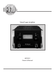
Tube Power Amplifier MC2301 Owner’s Manual McIntosh Laboratory, Inc.
The lightning flash with arrowhead, within an equilateral triangle, is intended to alert the user to the presence of uninsulated “dangerous voltage” within the product’s enclosure that may be of sufficient magnitude to constitute a risk of electric shock to persons. WARNING - TO REDUCE RISK OF FIRE OR ELECTRICAL SHOCK, DO NOT EXPOSE THIS EQUIPMENT TO RAIN OR MOISTURE. IMPORTANT SAFETY INSTRUCTIONS! PLEASE READ THEM BEFORE OPERATING THIS EQUIPMENT. 1. Read these instructions. 2. Keep these instructions. 3.
IMPORTANT! INSTRUCTIONS FOR REMOVAL OF FOAM INSERTS OVER THE VACUUM TUBES PRIOR TO CONNECTING THE A.C. POWER SUPPLY CORD, START ON THE NEXT PAGE.
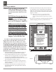
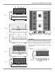
Unpacking the MC2301 Caution: To prevent damage to the MC2301 Tubes during shipping, there is a special foam insert surrounding the Tubes located on both sides of the Power Amplifier. BOTH Foam Inserts must be removed from the MC2301 before connecting the AC Power Supply Cord to the power amplifier. 6. Carefully reinstall the previously removed Tube Covers and chassis screws on both sides of the MC2301. Make sure the metal tabs located on the bottom of the Tube Cover are inserted into the chassis slots.
Unpacking the MC2301 and Ventilation Figure 3 Figure 4 Foam Insert Figure 8 Figure 5 Ventilation Adequate ventilation extends the trouble free life of the MC2301. Always allow air to flow through the ventilation holes on the bottom of the amplifier and a means for the warm air to escape at the top. Refer to figure 9 and the information on the next page for placement and installation of the MC2301.
Thank You Table of Contents Your decision to own this McIntosh MC2301 Tube Power Amplifier ranks you at the very top among discriminating music listeners. You now have “The Best.” The McIntosh dedication to “Quality,” is assurance that you will receive many years of musical enjoyment from this unit. Please take a short time to read the information in this manual. We want you to be as familiar as possible with all the features and functions of your new McIntosh. Safety Instructions .......................
Connector Information, Introduction and Performance Features Connector and Cable Information XLR Connectors Below is the Pin configuration for the XLR Balanced Input, Input/Output Connectors on the MC2301. Refer to the PIN 3 diagram for connection: PIN 1 PIN 2 PIN 1: Shield/Ground PIN 2: + Output PIN 3: - Output Power Control Connector The MC2301 Power Control Input receives an On/Off signal from +5 to +12 volts.
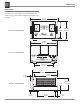
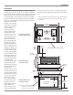
Dimensions Dimensions The following dimensions can assist in determining the best location for your MC2301. There is additional information on page 9 pertaining to installing the MC2301 into cabinets. 17-3/4" 45.09cm 11" Front View of the MC2301 27.94cm 12-5/16" 31.27cm 17-3/8" 44.15cm Rear View of the MC2301 12-1/4" 31.11cm 21" 54.61cm 20" 1-5/8" 50.86cm 4.12cm 10-1/2" 3/16" 0.48cm Side View of the MC2301 1-1/2" 3.81cm 8 15-3/4" 40.00cm 1-3/4" 4.45cm 26.
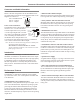
Installation Installation for clearance. Be sure to cut out a ventilation hole in the The MC2301 can be placed upright on a table or shelf, mounting shelf according to the dimensions in the drawstanding on its four feet. It also can be custom installed in ing. a piece of furniture or cabinet of your choice. The four feet may be removed from the bottom of the MC2301 when it is 1 When the MC2301 is installed together with other McIntosh custom installed as outlined below.
Notes 10
Rear Panel Connections and Switch INPUT MODE switch selects between balanced or unbalanced input Main Fuse holder, refer to information on the back panel of your MC2301 to determine the correct fuse size and rating OUTPUT Connections for 2 ohm Loudspeaker OUTPUT Connections for 4 ohm Loudspeaker OUTPUT Connections for 8 ohm Loudspeaker Caution: The Loudspeaker Negative Connections are above chassis ground.
How to Connect Caution: The supplied AC Power Cord should not be connected to the Rear Panel of the MC2301 Tube Power Amplifier until after the Loudspeaker Connections have been made. Failure to observe this could result in Electric Shock. For additional instruction on making Loudspeaker Connections contact your McIntosh Dealer or McIntosh Technical Support. 1. For Remote Power Control, connect a power control cable from the Control Center or Preamplifier Power Control Out to the MC2301 POWER CONTROL IN. 2.
How to Connect McIntosh Preamplifier McIntosh Loudspeaker Connect to AC Outlet 13
How to Connect for Bi-Amp Caution: The supplied AC Power Cord should not be connected to the Rear Panel of the MC2301 Tube Power Amplifier until after the Loudspeaker Connections have been made. Failure to observe this could result in Electric Shock. For additional instruction on making Loudspeaker Connections contact your McIntosh Dealer or McIntosh Technical Support. 1.
How to Connect for Bi-Amp McIntosh Preamplifier McIntosh Loudspeaker Connect to AC Outlet McIntosh Power Amplifier Two 15
Front Panel Displays and Controls Meter indicates the Power Output of the Amplifier Standby Power On and Sentry Monitor Tube Protection Activation Indicator METER Switch selects the display modes of the Power Output Meter and Meter Illumination 16 POWER Switch Turns AC Power On/Off, or On/Remote
How to Operate How to Operate Power On To have the MC2301 automatically turn On or Off when a control center turns on or off, rotate the power switch to the remote position. For manual operation, rotate the power switch to the On or Off position as desired. Refer to figure 8. Note: There must be a power control connection between the MC2301 and the McIntosh Control Center, in order for the remote power turn-on to function.
Technical Description McIntosh Laboratory, the company who introduced the world’s first amplifier that could be called “High Fidelity”, has done it again. The McIntosh engineering staff has created a tube power amplifier without compromise, using the most advanced McIntosh circuit design concepts. A continuous average power output rating of 300 watts makes this not only the most advanced, but also one of the most powerful tube amplifiers McIntosh has ever manufactured.
Technical Description MC2301 Design The design philosophy incorporated in the MC2301 involved several different techniques, all based on sound scientific logic. Every stage of voltage amplification must be as linear as possible prior to the use of negative feedback. McIntosh engineers know how to properly design negative feedback circuits so they contribute to the low distortion performance expected from a McIntosh amplifier. Refer to figure 12.
Technical Description, con’t feedback designs. The fully Balanced Push-Pull design is used from input to output. The resulting fully balanced configuration cancels many forms of audible distortion and greatly improves the Signal-to-Noise ratio of the amplifier. While conventional designs only take output from the plate, the Patented Unity Coupled Power Amplifier Circuitry takes the Power Output from both the plate and cathode of the Power Output Tubes.
Technical Description, con’t should fail. During normal operation there is absolutely no compromise in sonic performance with this circuit, and it ensures safe operation of the amplifier under even the most extreme operating conditions. In the event a problem occurs, the MC2301 Sentry Monitor Tube Protection Circuitry will activate to prevent potentially destructive high levels of current from flowing in the amplifier. the next power amplifier occurs at a later time.
Specifications Specifications Power Output Minimum sine wave continuous average power output is: 300 watts into 2 ohm load 300 watts into 4 ohm load 300 watts into 8 ohm load Output Load Impedance 2, 4 or 8 ohms Rated Power Band 20Hz to 20,000Hz Total Harmonic Distortion 0.5% maximum harmonic distortion at any power level from 250 milliwatts to rated power, 20Hz to 20,000Hz Frequency Response +0, -0.5dB from 20Hz to 20,000Hz +0, -3.0dB from 10Hz to 100,000Hz Input Sensitivity (for rated output) 1.
Packing Instructions Packing Instructions In the event it is necessary to repack the equipment for shipment, the equipment must be packed exactly as shown below. It is very important that the four feet are attached to the bottom of the equipment. This will ensure the proper equipment location on the bottom foam pad. Failure to do this will result in shipping damage. To protect the tubes during shippment, the two Foam Inserts removed from the MC2301 need to be re-inserted.
McIntosh Laboratory, Inc. 2 Chambers Street Binghamton, NY 13903 The continuous improvement of its products is the policy of McIntosh Laboratory Incorporated who reserve the right to improve design without notice. Printed in the U.S.A. McIntosh Part No.