Power Amplifier MC252 Owner’s Manual McIntosh Laboratory, Inc.
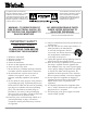
The lightning flash with arrowhead, within an equilateral triangle, is intended to alert the user to the presence of uninsulated “dangerous voltage” within the product’s enclosure that may be of sufficient magnitude to constitute a risk of electric shock to persons. WARNING - TO REDUCE RISK OF FIRE OR ELECTRICAL SHOCK, DO NOT EXPOSE THIS EQUIPMENT TO RAIN OR MOISTURE. IMPORTANT SAFETY INSTRUCTIONS! PLEASE READ THEM BEFORE OPERATING THIS EQUIPMENT. 1. Read these instructions. 2. Keep these instructions. 3.
Thank You Table of Contents Your decision to own this McIntosh MC252 Power Amplifier ranks you at the very top among discriminating music listeners. You now have “The Best.” The McIntosh dedication to “Quality,” is assurance that you will receive many years of musical enjoyment from this unit. Please take a short time to read the information in this manual. We want you to be as familiar as possible with all the features and functions of your new McIntosh. Safety Instructions .............................
Connector Information XLR Connectors Below is the Pin configuration for the XLR Balanced Input Connectors on the MC252. Refer to the diagram for connection: PIN 1: Shield/Ground Pin 1 Pin 2 PIN 2: + Input Pin 3 PIN 3: - Input Power Control and Trigger Connectors The MC252’s Power Control Outputs provide a 5 volt signal. Use a 1/8 inch stereo mini phone plug to connect to the Positive Power Control Input on other N/C McIntosh Components.
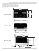
Connector Information, Introduction, Performance Features and Dimensions The following dimensions can assist in determining the best location for your MC252. There is additional information on the next page pertaining to installing the MC252 into cabinets. 17-1/2" 44.45cm 8-13/16" 22.38cm Front View of the MC252 9-7/16" 23.97cm 16-13/16" 42.70cm Rear View of the MC252 13-1/4" 33.66cm 14-1/2" 36.83cm 13-5/8" 34.61cm Side View of the MC252 8-1/8" 20.64cm 8-3/16" 21.11cm 7/8" 2.
Installation Installation Caution: The MC252 Amplifier weight is 94.5 pounds (42.87 kilograms). It requires two or more persons to safely handle when moving the amplifier. (40.64 cm) depth behind the front panel. Allow 1-3/16 inches (3.02 cm) in front of the mounting panel for knob clearance. Be sure to cut out a ventilation hole in the mounting shelf according to the dimensions in the drawing. The MC252 can be placed upright on a table or shelf, standing on its four feet.
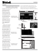
Top Panel Connections and Switch Main Fuse holder, refer to information on the top back panel of the MC252 to determine the correct fuse size and rating POWER CONTROL IN receives a turn On/Off Trigger from a McIntosh component. POWER CONTROL OUT sends a turn On/ Off Trigger to the next McIntosh component RIGHT Channel OUTPUTs connections for 2 ohm, 4 ohm and 8 ohm Loudspeakers Connect the MC252 power cord to a live AC outlet.
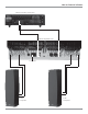
How to Connect in Stereo Caution: The supplied AC Power Cord should not be connected to the Rear Panel of the MC252 Amplifier until after the Loudspeaker Connections have been made and the supplied protective Terminal Connection Covers have been installed. Failure to observe this could result in Electric Shock. 1. For Remote Power Control, connect a power control cable from the Control Center or Preamplifier Power Control Out to the MC252 Power Control In. 2.
How to Connect in Stereo McIntosh C45 Audio Control Center MC252 Top Rear View To AC Outlet 4 ohm Loudspeaker 4 ohm Loudspeaker 9
How to Connect in Mono Bridged Mode Caution: The supplied AC Power Cord should not be connected to the Rear Panel of the MC252 Amplifier until after the Loudspeaker Connections have been made and the supplied protective Terminal Connection Covers have been installed. Failure to observe this could result in Electric Shock. There are two different ways of operating the MC252 monaurally, Mono Bridged Mode and Mono Bi-Amp (Parallel) Mode.
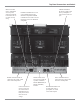
How to Connect in Mono Bridged Mode McIntosh C45 Audio Control Center MC252 Top Rear View To AC Outlet Mono Bridge Hookup Connections 4 ohm Loudspeaker Loudspeaker Loudspeaker Negative Impedance (-) Connection Loudspeaker Positive (+) Connection 4S (Ohm) Left Output 2S Positive (+ ) Connection Right Output 2S Positive (+ ) Connection 8S (Ohm) Left Output 4S Positive (+ ) Connection Right Output 4S Positive (+ ) Connection 16S (Ohm) Left Output 8S Positive (+ ) Connection Right Output 8S Posi
How to Connect in Mono Bi-Amp (Parallel) Mode Caution: The supplied AC Power Cord should not be connected to the Rear Panel of the MC252 Amplifier until after the Loudspeaker Connections have been made and the supplied protective Terminal Connection Covers have been installed. Failure to observe this could result in Electric Shock. There are two different ways of operating the MC252 monaurally, Mono Bridged Mode and Mono Bi-Amp (Parallel) Mode.
How to Connect in Mono Bi-Amp (Parallel) Mode McIntosh C45 Audio Control Center additional instruction on making Loudspeaker Connections contact your McIntosh Dealer or McIntosh Technical Support. 5. Attach the supplied Terminal Connection Covers with the four Mounting Screws (6-32 x 1/4 inch Phillips Head) to the Rear Panel of the MC252 Amplifier. Refer to figure 9.
Front Panel Displays and Controls METER indicates the Power Output of the Left Channel Amplifier METER indicates the Power Output of the Right Channel Amplifier Remote On Indicator lights when the amplifier is in the Remote Turn-On Mode METER Switch selects the display modes of the Power Output Meter POWER GUARD LED lights when the amplifier Left Channel POWER GUARD circuit activates 14 POWER Switch Turns AC power On/Off, or On/Remote POWER GUARD LED lights when the amplifier Right Channel POWER GUA
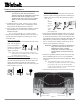
How to Operate How to Operate Power On To have the MC252 automatically turn On or Off when a control center turns on or off, rotate the power switch to the remote position. For manual operation, rotate the power switch to the On or Off position as desired. Refer to figure 10. Note: There must be a power control connection between the MC252 and Figure 10 the McIntosh Control Center, in order for the remote power turn-on to function.
Technical Description McIntosh Laboratory, the company who introduced the world’s first amplifier that could be called “High Fidelity”, has done it again. The McIntosh engineering staff has created a power amplifier without compromise, using the most advanced McIntosh circuit design concepts. A continuous average power output rating of 250 watts and with an output current of greater than 50 amperes per channel, making this one of the most advanced and powerful amplifiers McIntosh has ever manufactured.
Technical Description rent gain over the entire current range they must cover. Output transistors in particular, have matched uniform current gain, high current-bandwidth product and large active region safe operating area. An automatic tracking bias system completely eliminates any trace of crossover distortion. Precision metal film resistors and low dielectric absorption film capacitors are used in all critical circuit locations.
lower than optimum, causes more output current to flow, which results in extra heat being generated in the power output stage. This increase in temperature will result in a reduced life expectancy for the amplifier. The Autoformer creates an ideal match between the power amplifier output stage and the loudspeaker. Refer to figure 15. There is absolutely no performance limitation Figure 15 with an Autoformer.
Technical Description, con’t tronic attenuator at the amplifier input reduces the input volume just enough to prevent any further increase in distortion. The Power Guard circuit acts so fast that there are absolutely no audible side effects and the sonic purity of the music reproduction is perfectly preserved.
Notes 21
Specifications Specifications Power Output Stereo Minimum sine wave continuous average power output per channel, all channels operating is: 250 watts into 2 ohm load 250 watts into 4 ohm load 250 watts into 8 ohm load A-Weighted Signal To Noise Ratio 112dB below rated output Power Output Mono Bridged Minimum sine wave continuous average power output is: 500 watts into 4 ohm load 500 watts into 8 ohm load 500 watts into 16 ohm load Wide Band Damping Factor Greater than 40 Power Output Mono Bi-Amp (Parall
Packing Instructions Packing Instructions In the event it is necessary to repack the equipment for shipment, the equipment must be packed exactly as shown below. It is very important that the four plastic feet are attached to the bottom of the equipment. Three #10 x 2-1/2 inch screws and washers must be used to fasten the unit securely to the bottom pad and shipping skid. This will ensure the proper equipment location on the bottom pad. Failure to do this will result in shipping damage.
McIntosh Laboratory, Inc. 2 Chambers Street Binghamton, NY 13903 The continuous improvement of its products is the policy of McIntosh Laboratory Incorporated who reserve the right to improve design without notice. Printed in the U.S.A. McIntosh Part No.