Owners Manual MC602 Power Amplifier MC602 McIntosh Laboratory, Inc.
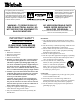
The lightning flash with arrowhead, within an equilateral triangle, is intended to alert the user to the presence of uninsulated dangerous voltage within the products enclosure that may be of sufficient magnitude to constitute a risk of electric shock to persons. WARNING - TO REDUCE RISK OF FIRE OR ELECTRICAL SHOCK, DO NOT EXPOSE THIS EQUIPMENT TO RAIN OR MOISTURE. IMPORTANT SAFETY INSTRUCTIONS! PLEASE READ THEM BEFORE OPERATING THIS EQUIPMENT. General: 1. Read these instructions. 2.
A polarized plug has two blades with one wider than the other. A grounding type plug has two blades and a third grounding prong. The wide blade or the third prong are provided for your safety. If the provided plug does not fit into your outlet, consult an electrician for replacement of the obsolete outlet. 18. Do not overload wall outlets, extension cords or integral convenience receptacles as this can result in a risk of fire or electric shock. 19.
Table of Contents Introduction Safety Instructions ............................................................ 2 Thank You and Please Take a Moment............................. 3 Technical Assistance and Customer Service .................... 3 Table of Contents and General Notes ............................... 4 Introduction ...................................................................... 4 Performance Features ....................................................... 4 Dimensions ...................
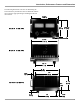
Introduction, Performance Features and Dimensions The following dimensions can assist in determining the best location for your MC602. There is additional information on the next page pertaining to installing the MC602 into cabinets. 17-3/4" 45.09cm 11" Front View of the MC602 12-5/16" 27.94cm 31.27cm 17-3/8" 44.15cm Rear View of the MC602 12-1/4" 31.11cm 19-1/2" 49.50cm 18" 1-5/8" 45.72cm 4.12cm Side View of the MC602 10-1/2" 3/16" 26.70cm 0.48cm 1-1/2" 3.81cm 14" 35.60cm 1-9/16" 3.
Installation Installation Caution: The MC602 Amplifier weight is 155 pounds (70.31 kilograms). It requires two or more persons to safely handle when moving the amplifier. Allow 2 inches (5.08 cm) in front of the mounting panel for handle clearance. Be sure to cut out a ventilation hole in the mounting shelf according to the dimensions in the drawing. The MC602 can be placed upright on a table or shelf, standing on its four feet.
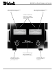
MC602 Rear Panel Connections and Switch BALANCED INPUTS for audio cables from a preamplifier or control center audio outputs POWER CONTROL IN receives turn on/off signals from a McIntosh component and the POWER CONTROL OUT sends a turn On/ Off signal to the next McIntosh component UNBALANCED INPUTS for audio cables from a preamplifier or control center audio output INPUT MODE switch selects balanced or unbalanced inputs CIRCUIT BREAKER Press to reset if the amplifier will not power up Connect the MC60
How to Connect the MC602 Caution: The supplied AC Power Cord should not be connected to the Rear Panel of the MC602 Amplifier until after the Loudspeaker Connections have been made and the supplied protective Terminal Connections Cover has been installed. Failure to observe this could result in Electric Shock. 1. For Remote Power Control, connect a power control cable from the Control Center or Preamplifier Power Control Out to the MC602 Power Control In. 2.
How to Connect the MC602 McIntosh C200C Controller McIntosh C200P Preamplifier To AC Outlet Right Loudspeaker 4 ohm Left Loudspeaker 4 ohm Caution: The Loudspeaker Negative Connections are above chassis ground and are not common between channels. Do not combine any connections together or ground them.
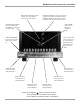
MC602 Front Panel Displays and Controls METER indicates the Left Channel Power Output of the amplifier METER indicates the Right Channel Power Output of the amplifier POWER GUARD LEDs light when the amplifier channel POWER GUARD circuit activates Remote On Indicator lights when the amplifier is in the Remote Turn-On Mode METER Switch selects the display modes of the power output meters 10 POWER Switch Turns AC power On/Off, or On/Remote
How to Operate the MC602 How to Operate the MC602 Power On To have the MC602 automatically turn On or Off when a control center turns on or off, rotate the power switch to the remote position. For manual operation, rotate the power switch to the On or Off position as desired. Refer to figure 8. Note: There must be a power control connection between the MC602 and the McIntosh Control Center, in order for the remote power turn-on to function.
Technical Description McIntosh Laboratory, the company who introduced the worlds first amplifier that could be called High Fidelity, has done it again. The McIntosh engineering staff has created a power amplifier without compromise, using the most advanced McIntosh circuit design concepts.
Technical Description not come easily. Many months of design, testing and measuring were required. Extensive controlled listening tests, the ultimate form of measuring, were made before the final design was accepted. Design Philosophy The design philosophy incorporated in the MC602 involved several different techniques, all based on sound scientific logic. Every stage of voltage or current amplifica- tion must be as linear as possible prior to the use of negative feedback.
balanced circuitry. The resulting double balanced configuration cancels even order distortion. Refer to figure 12 on page 13. All transistors are selected to have nearly constant current gain over the entire current range they must cover. Output transistors in particular, have matched uniform current gain, high current bandwidth product and large active region safe operating area. An automatic tracking bias system completely eliminates any trace of crossover distortion.
Technical Description, cont Without Power Guard able, since it can damage valuable loudspeaker system tweeters. You will never experience the harsh and damaging distortion due to clipping. The Power Guard circuit is a waveform comparator, monitoring both the input and output waveforms. Under normal operating conditions, there are no differences Figure 16 between the shape of these waveforms. If an amplifier channel is overdriven, there will be a difference between the two signal waveforms.
Notes 17
Specifications Specifications Power Output Minimum sine wave continuous average power output per channel, all channels operating is: 600 watts into 2 ohm load 600 watts into 4 ohm load 600 watts into 8 ohm load Rated Power Band 20Hz to 20,000Hz Total Harmonic Distortion Maximum Total Harmonic Distortion at any power level from 250 milliwatts to rated power output is: 0.005% for 2, 4 or 8 ohm loads Dynamic Headroom 2.1dB Frequency Response +0, -0.
Packing Instructions Packing Instructions In the event it is necessary to repack the equipment for shipment, the equipment must be packed exactly as shown below. It is very important that the four feet are attached to the bottom of the equipment. This will ensure the proper equipment location on the bottom foam pad. Failure to do this will result in shipping damage. Use the original shipping carton and interior parts only if they are all in good serviceable condition.
McIntosh Laboratory, Inc. 2 Chambers Street Binghamton, NY 13903 McIntosh Part No.