
Owner's Manual Power Amplifier MC602


14
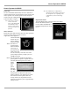
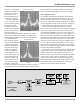
Figure 15
Input Test Signal
balanced circuitry. The resulting double balanced configu-
ration cancels even order distortion. Refer to figure 12 on
page 13.
All transistors are selected to have nearly constant cur-
rent gain over the entire current range they must cover.
Output transistors in particular, have matched uniform cur-
rent gain, high current bandwidth product and large active
region safe operating area. An automatic tracking bias sys-
tem completely eliminates any trace of crossover distor-
tion. Precision metal film resistors and low dielectric ab-
sorption film capacitors are used in all critical circuit loca-
tions.
The output signals of the two balanced circuits are
coupled together in the unique McIntosh MC602 Output
Autoformer. It provides low distortion power transfer at
frequencies from below 20Hz to well beyond 20,000Hz
with optimum impedance points of two ohms, four ohms
and eight ohms. The unequaled expertise of McIntosh in
the design and manufacturing of autoformers is legendary
in the high fidelity industry.
The high efficiency circuit design of the MC602 con-
tributes to low operating temperatures. More than 290
square inches of heat sink area keep the MC602 operating
safely with convection cooling. No fans are needed.
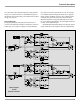
Autoformers
All solid state power amplifier output circuits work best
into what is called an optimum load. This optimum load
may vary considerably from what a loudspeaker requires.
In the case of more than one loudspeaker connected in par-
allel, the load to the power amplifier may drop to two ohms
or even less. A power amplifier connected to a load that is
lower than optimum, causes more output current to flow,
which results in extra heat being generated in the power
output stage. This increase in temperature will result in a
reduced life expectancy for the amplifier.
The Autoformer creates an ideal match between the
power amplifier output stage and the loudspeaker. A McIn-
tosh amplifier with an Autoformer can be used to safely
drive multiple speakers without reducing the life expect-
ancy of the
power ampli-
fier. Refer to
figure 13.
There is ab-
solutely no per-
formance limi-
tation with an
Autoformer. Its
frequency re-
Figure 13
sponse exceeds that of the output circuit itself, and extends
well beyond the audible range. Its distortion level is so low
it is virtually impossible to measure.
In the rare event of a power amplifier output circuit fail-
ure, the McIntosh Autoformer provides absolute protection
from possible damage to your valuable loudspeakers. The
unequaled expertise of McIntosh in the design and manu-
facturing of Autoformers is legendary in the high fidelity
industry. McIntosh engineers know how to do it right.
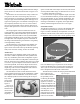
Protection Circuits
The MC602 incorporates its version of the McIntosh Sen-
try Monitor output transistor protection circuit. Refer to
Figure 14. There is absolutely no compromise in sonic per-
formance with this circuit, and it ensures safe operation of
the amplifier under even the most extreme operating condi-
tions. The different types of protection circuits incorpo-
rated in the MC602 insure a long and safe operating life.
This is just one of the many characteristics of McIntosh
Power Amplifiers that make them world famous.
The MC602 also includes the unique patented McIntosh
Power Guard circuit.
Power Guard eliminates
the possibility of ever
overdriving the amplifier
into clipping. Refer to
figures 15, 16 and 17. An
overdriven amplifier can
produce both audible and
inaudible distortion levels
exceeding 40%. The au-
dible distortion is un-
pleasant to hear, but the
inaudible ultrasonic dis-
tortion is also undesir-
Figure 14