MCC302 Power Amplifier MCC302M Owner’s Manual McIntosh Laboratory, Inc.
WARNING - TO REDUCE RISK OF FIRE OR ELECTRICAL SHOCK, DO NOT EXPOSE THIS EQUIPMENT TO RAIN OR MOISTURE. NO USER-SERVICEABLE PARTS INSIDE. REFER SERVICING TO QUALIFIED PERSONNEL. To prevent the risk of electric shock, do not remove bottom cover. No user serviceable parts inside. IMPORTANT SAFETY INSTRUCTIONS! PLEASE READ THEM BEFORE OPERATING THIS EQUIPMENT. General: 1. Read these instructions. 2. Keep these instructions. 3. Heed all warnings. 4. Follow all instructions. 5.
Thank You Table of Contents Your decision to own this McIntosh MCC302 Two Channel Power Amplifier ranks you at the very top among discriminating music listeners. You now have “The Best.” The McIntosh dedication to “Quality,” is assurance that you will receive many years of musical enjoyment from this unit. Please take a short time to read the information in this manual. We want you to be as familiar as possible with all the features and functions of your new McIntosh. Safety Instructions ................
Introduction Now you can take advantage of traditional McIntosh standards of excellence in the MCC302 Power Amplifier. Two 150 watt high current output channels will drive any high quality loudspeaker system to its ultimate performance. The MCC302 reproduction is sonically transparent and absolutely accurate. The McIntosh Sound is “The Sound of the Music Itself.
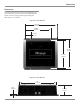
Dimensions Dimensions The following dimensions can assist in determining the best location for your MCC302. There is additional information on the next page pertaining to installing the MCC302 into your vehicle. Top View of the MCC302 13-21/32" 34.69cm 11.00" 27.94cm 2-11/16" 6.82cm 12-1/2" 31.75cm 11-7/8" 30.16cm Side View of the MCC302 11" 27.93cm 11/32" 10.93cm 2-15/16" 7.
Installation Installation It is recommended that a professional who is skilled in all aspects of installation and operation install the MCC302 and any associated mobile audio equipment. Amplifier Ventilation Always provide adequate ventilation for the MCC302. The amplifier requires an adequate airflow into the cooling fans, which are located on the left side of the amplifier. The warm air exits the amplifier through vents on the heatsinks. See figure 1.
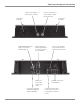
Side Panel Cooling and Connections Connect to the Negative (-) vehicle battery terminal Connect to the positve (+) vehicle battery terminal with an inline fuse Cooling Fan Air Intake Cooling Fan Air Intake SUBWOOFER OUTPUTS supply a two channel summed output OUTPUTs from the INPUT Signal Source to connect to another Power Amplifier INPUTs for audio cables from a signal source Connector for optional SUBwoofer REMOTE Volume CONTROL Receives the Amplifier Turn-ON signal from a McIntosh Control Center
How to Connect for Two Channels How to Connect for Two Channels 1. Connect a wire from the Control Center Amp On to the MCC302 ON Connector on the right side of the amplifier. Note: The Subwoofer Outputs are line-level outputs and summed from all the Input Channels. They can be remotely controlled by connecting a cable from the SUB REMOTE CONTROL jack to the Optional External Rotary Control. Note: All cables should be connected to the amplifier before connecting the DC power cables to the battery. 2.
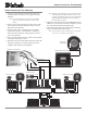
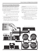
How to Connect for Bridged Subwoofer Mode How to Connect for Bridged Subwoofer Mode There are many different possible Vehicle Audio System combinations utilizing the MCC302 Power Amplifier. It is recommended that a professional who is skilled in all aspects of Vehicle Audio Systems assist you in the selection and installation. The illustration below is just one of the many possible combinations. 1. Connect a wire from the Control Center Amp On to the MCC302 ON Connector on the right side of the amplifier.
Top Panel Controls, Display and Switches EQUALIZER Controls select the Frequency and the Level of Boost or Cut at the Center Frequencies for Channels 1 and 2 CROSSOVER Filter Switch and Control select the low roll-off frequency, high roll-off frequency or flat frequency response MODE Switch selects STEREO or BRIDGE mode of operation 10 POWER GUARD LED lights when the Power Guard Circuit activates for Amplifier Channels 1 or 2 SENSITIVITY Individual Input Sensitivity Controls for Channels 1 and 2 SOUR
How to Operate Introduction The McIntosh MCC302 is a highly versatile amplifier that can be configured in many ways. This manual gives examples of some of the most common configurations. The best way to set equalization and filter controls is through the use of a real-time spectrum analyzer and the expertise of a professional installer. This manual will guide you through the basic operation, however we suggest you refer to your dealer for further information on the use of this unit.
How to Replace the Fuses How to Replace the Fuses If the MCC302 produces no sound, there is no Illumination of the Nomenclature on the Top Glass Panel, and the power connections seem secure, one or more of the Amplifier’s Fuse(s) may have failed. Under normal operating conditions your amplifier’s fuses should not fail. Failure of a fuse is usually an indication of a problem. Replacing the fuse, if there is problem in the amplifier, may incur a risk of further damage. Refer to figures 9, 10 and 11.
MCC302 Block Diagram Block Diagram 13
Specifications Specifications Power Output Per Channel 150 watts into 4 ohm loads and 300 watts into 2 ohm loads is the minimum sine wave continuous average power output per channel, with both channels operating. Power Output Bridged 600 watts into 4 ohm loads is the minimum sine wave continuous average power output. Rated Power Band 20Hz to 20,000Hz Total Harmonic Distortion Maximum Total Harmonic Distortion at any power level from 250 milliwatts to rated power output is: 0.005% for 4 ohm loads 0.
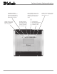
Packing Instructions Packing Instructions In the event it is necessary to repack the equipment for shipment, the equipment must be packed exactly as shown below, failure to do so will result in shipping damage. Make sure that the Top Glass Panel is firmly secured to the chassis using the supplied hex head screws. Use the original shipping carton and interior parts only if they are all in good serviceable condition.
McIntosh Laboratory, Inc. 2 Chambers Street Binghamton, NY 13903 The continuous improvement of its products is the policy of McIntosh Laboratory Incorporated who reserve the right to improve design without notice. Printed in the U.S.A. McIntosh Part No.