Power Amplifier MCC406M Owner’s Manual McIntosh Laboratory, Inc.
The lightning flash with arrowhead, within an equilateral triangle, is intended to alert the user to the presence of uninsulated “dangerous voltage” within the product’s enclosure that may be of sufficient magnitude to constitute a risk of electric shock to persons. WARNING - TO REDUCE RISK OF FIRE OR ELECTRICAL SHOCK, DO NOT EXPOSE THIS EQUIPMENT TO RAIN OR MOISTURE.
Thank You Table of Contents Your decision to own this McIntosh MCC406M Six Channel Power Amplifier ranks you at the very top among discriminating music listeners. You now have “The Best.” The McIntosh dedication to “Quality,” is assurance that you will receive many years of musical enjoyment from this unit. Please take a short time to read the information in this manual. We want you to be as familiar as possible with all the features and functions of your new McIntosh. Safety Instructions ...............
Important Information 1. An optional McIntosh External Subwoofer Rotary Control, Model Number R1163, is available from your McIntosh Dealer. 2. Do not connect the Amplifier Speaker Negative Terminal Connection directly to the Vehicle Chassis. Failure to observe this could result in damage to your Amplifier. 3. For additional connection information, refer to the owner’s manual(s) for any component(s) connected to the MCC406M Amplifier. 4.
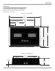
Dimensions Dimensions The following dimensions can assist in determining the best location for your MCC406M. There is additional information on the next page pertaining to installing the MCC406M into your vehicle. Top View of the MCC406M 18-3/8" 46.66cm 15-3/16" 38.57cm 9-3/16" 3-3/16" 23.33cm 8.09cm 12-1/4" 31.12cm 11-13/16" 29.97cm Side View of the MCC406M 11" 27.93cm 11/32" 10.93cm 2-15/16" 7.
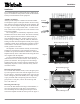
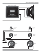
Installation Installation It is recommended that a professional who is skilled in all aspects of installation and operation install the MCC406M and any associated mobile audio equipment. Amplifier Ventilation Always provide adequate ventilation for the MCC406M. The amplifier requires an adequate airflow into the cooling fans, which are located on the left side of the amplifier. The warm air exits the amplifier through vents on the heatsinks. See figure 1.
Side Panel Cooling and Connections Connect to the Negative (-) vehicle battery terminal Connect to the positve (+) vehicle battery terminal with an inline fuse Cooling Fan Air Intake INPUTs for audio cables from a signal source Cooling Fan Air Intake Receives the Amplifier Turn-ON signal from a McIntosh Control Center OUTPUT Connections for 2, 4 or 8 ohm loudspeakers Connector for optional Subwoofer Remote Volume Control OUTPUT Connections for 2, 4 or 8 ohm loudspeakers Controls the Power Guard Ci
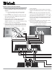
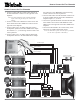
How to Connect for Six Channels 1. Connect a cable from the Control Center Amp On to the MCC406M ON Connector on the right side of the amplifier. Note: All cables should be connected to the amplifier before connecting the DC power cables to the battery. 2. Connect a cable from a McIntosh Control Center with Power Guard to the MCC406M PG Connector on the right side of the amplifier. 3.
How to Connect for Six Channels McIntosh Mono Power Amplifier (+) Subwoofer (-) (-) (+) (-) (+) (+) (-) (+) Right Front Tweeter Right Front Midrange (-) Right Front Woofer (-) (+) (+) Left Front Tweeter Left Front Midrange (-) Left Front Woofer 9
How to Connect for Five Channels How to Connect for Five Channels 1. Connect a cable from the Control Center Amp On to the MCC406M ON Connector on the right side of the amplifier. Note: All cables should be connected to the amplifier before connecting the DC power cables to the battery. 2. Connect a cable from a McIntosh Control Center with Power Guard to the MCC406M PG Connector on the right side of the amplifier. 3.
How to Connect for Four Channels How to Connect for Four Channels 1. Connect a cable from the Control Center Amp On to the MCC406M ON Connector on the right side of the amplifier. fier Channels 5 and 6 Outputs being careful to observe the correct polarities. 5. Connect audio cables from the McIntosh Control Center Front and Rear Outputs to the MCC406M Power Amplifier Inputs 1, 2, 3 and 4. Note: All cables should be connected to the amplifier before connecting the DC power cables to the battery.
How to Connect for Three Channels 1. Connect a cable from the Control Center Amp On to the MCC406M ON Connector on the right side of the amplifier. Note: All cables should be connected to the amplifier before connecting the DC power cables to the battery. 2. Connect a cable from a McIntosh Control Center with Power Guard to the MCC406M PG Connector on the right side of the amplifier. 3.
How to Connect for Three Channels Right Loudspeaker System Left Loudspeaker System Subwoofer 13
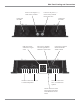
Top Panel Controls, Display and Switches CH 5-6 SENSITIVITY Individual Input Sensitivity Controls for Channels 5 and 6 CH 5-6 LOW PASS Filter Switch and Control select the high frequency roll-off or flat frequency response CH 5-6 MODE Switch selects STEREO or BRIDGED mode of operation CH 5-6 HIGH PASS Filter Switch and Control select the low frequency roll-off or flat frequency response POWER GUARD LED lights when the Power Guard Circuit activates for Amplifier Channels 5 or 6 INPUT SOURCE Switch for
How to Operate the MCC406M Introduction The McIntosh MCC406M is a highly versatile amplifier that can be configured in many ways. This manual gives examples of some of the most common configurations. The best way to set the filter controls is through the use of a real-time spectrum analyzer and the expertise of a professional installer. This manual will guide you through the basic operation, however we suggest you refer to your Dealer for further information on the use of this unit.
How to Operate in Six or Five Channel Mode How to Operate in Six Channel Mode How to Operate in Five Channel Mode In the 6 Channel Operating Mode, channels 1 thru 4 operate as independent 50 watt amplifiers; channels 5 and 6 each provide 100 watts of power output. A typical six channel application is to use an Electronic Crossover Network ahead of the MCC406M Power Amplifier and each amplifier channel powers Loudspeaker Drivers directly. A second power amplifier is used to drive the Subwoofer.
How to Operate in Four or Three Channel Mode How to Operate in Four Channel Mode How to Operate in Three Channel Mode In the 4 Channel Operating Mode channel pairs of (1 and 2) and (3 and 4) are bridged to provide 200 watts each. Channels 5 and 6 are driven independently for 100 watts output for each channel. Refer to figures 8 and 9, along with page 11 of this Owner’s Manual. In the 3 Channel Operating Mode channel pairs of (1 and 2), (3 and 4) and (5-6) are bridged.
How to Replace the Fuses How to Replace the Fuses If the MCC406M produces no sound, there is no Illumination of the Nomenclature on the Top Glass Panel, and the power connections seem secure, one or more of the Amplifier Fuse(s) may have failed. Under normal operating conditions your amplifier’s fuses should not fail. Failure of a fuse is usually an indication of a problem. Replacing the fuse, if there is problem in the amplifier, may incur a risk of further damage. Refer to figures 10, 11 and 12.
MCC406M Block Diagram MCC406M Block Diagram 19
Notes 21
Specifications Specifications Power Output Per Channel Channels 1 thru 4: 50 watts into 4 ohm loads or 100 watts into 2 ohm loads, is the minimum sine wave continuous average power output per channel all channels operating. Channels 5 and 6: 100 watts into 4 ohm loads or 200 watts into 2 ohm loads, is the minimum sine wave continuous average power output per channel all channels operating.
Packing Instructions Packing Instructions In the event it is necessary to repack the equipment for shipment, the equipment must be packed exactly as shown below, failure to do so will result in shipping damage. Make sure that the Top Glass Panel is firmly secured to the chassis using the supplied hex head screws. Use the original shipping carton and interior parts only if they are all in good serviceable condition.
McIntosh Laboratory, Inc. 2 Chambers Street Binghamton, NY 13903 The continuous improvement of its products is the policy of McIntosh Laboratory Incorporated who reserve the right to improve design without notice. Printed in the U.S.A. McIntosh Part No.