
Owner`s manual


4
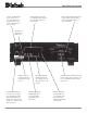
XLR Connectors:
Below is the Pin configuration for the XLR Balanced Ana-
log Audio Output Connectors on the MDA1000. Refer to
the diagram for connection:
PIN 1: Shield/Ground
PIN 2: + Signal
PIN 3: - Signal
Below is the Pin configuration for the XLR Balanced Digi-
tal Audio Input Connectors on the MDA1000. Refer to the
diagram for connection:
PIN 1: Shield/Ground
PIN 2: + Signal
PIN 3: - Signal
Power Control and Trigger Connectors
The MDA1000’s Power Control Outputs provide a 5 volt
signal. Use a 1/8 inch stereo mini phone
plug to connect to the Power Control In-
put on other McIntosh Components.
Data and IR Port Connectors
The MDA1000’s Data Port Output provides Remote Con-
trol Signals and the IR
Input Port allows for the
connection of other
brands IR Sensors. Use a
1/8 inch stereo mini
phone plug to connect to
the Data Port Inputs on
McIntosh Source Units.
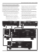
Connector InformationImportant Information
1. It is recommended that a qualified professional assist you in
the choice and installation of a McIntosh Audio System for
your home.
2. Before making any connections to the MDA1000, make sure
that the Main POWER Switch is in the Off position. When
the MDA1000 and other McIntosh Components are in their
Standby Mode the Microprocessor’s Circuitry inside each
component is active and communication is occurring
between them. Failure to do so could result in
malfunctioning of some or all of the system’s normal
operations.
3. The following Connecting Cable is available from the
McIntosh Parts Department:
Data and Power Control Cable Part No. 170-202
Six foot, 2 conductor shielded, with two 1/8 inch stereo
mini phone plugs.
4. When the MDA1000 Digital XLR Input is used to connect
with the Digital XLR Output of the McIntosh MCD1000 CD
Transport Component, it is important to use a twisted pair
shielded cable.
5. For additional connection information, refer to the owner’s
manual(s) for any component(s) connected to the
MDA1000.
6. With the LEVEL Control active, the MDA1000 is capable of
driving a power amplifier directly. When the MDA1000 is
connected to a Preamplifier Input and the LEVEL Control
is active, LEVEL Control settings above 81 (as indicated on
the Front Panel Alphanumeric Display) may cause some
Preamplifier Inputs to overload due to the high signal level.
Positive
N/C
Ground
IR Input Port Connector
Data Signal
Ground
N/C
Data Signal
N/C
Data Ground
Data Port Connector
Pin 1
Pin 2
Pin 3
Pin 1
Pin 2
Pin 3