Video Projector MDLP2 Owner’s Manual McIntosh Laboratory, Inc. 2 Chambers Street Binghamton, New York 13903-2699 Phone: 607-723-3512 www.mcintoshlabs.
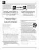
The lightning flash with arrowhead, within an equilateral triangle, is intended to alert the user to the presence of uninsulated “dangerous voltage” within the product’s enclosure that may be of sufficient magnitude to constitute a risk of electric shock to persons. WARNING - TO REDUCE RISK OF FIRE OR ELECTRICAL SHOCK, DO NOT EXPOSE THIS EQUIPMENT TO RAIN OR MOISTURE. IMPORTANT SAFETY INSTRUCTIONS! PLEASE READ THEM BEFORE OPERATING THIS EQUIPMENT. 1. Read these instructions. 2. Keep these instructions. 3.
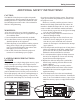
Safety Instructions ADDITIONAL SAFETY INSTRUCTIONS! CAUTION: The MDLP2 Video Projector weight is 40 pounds (18.14 kilograms). When mounting the projector to a building structure it is important to follow all of the local building/construction codes. Not evaluated for Wall or Ceiling Mounting. WARNINGS: A. Do not remove the cover from the equipment. B. Do not insert anything into the equipment through the ventilation holes. C. Do not handle the mains lead with wet hands. D.
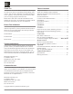
Thank You Table of Contents Your decision to own this McIntosh MDLP2 Video Projector ranks you at the very top among discriminating video viewers. You now have “The Best.” The McIntosh dedication to “Quality,” is assurance that you will receive many years of viewing enjoyment from this unit. Please take a short time to read the information in this manual. We want you to be as familiar as possible with all the features and functions of your new McIntosh. Safety Instructions................................
General Information General Information CAUTION: To prevent possible damage to the Projector Lens Assembly, DO NOT at any time attempt to LIFT, CARRY or RE-ORIENT the Projector using the Lens. 1. The Main AC Power going to the MDLP2 and any other McIntosh Component(s) should not be applied until all the system components are connected together. Failure to do so could result in malfunctioning of some or all of the system’s normal operations.
Connector and Cable Information Power Control Connectors The MDLP2 Power Control Output Jacks send and Power Control Input Jacks receive Power On/Off Signals when connected to McIntosh and other nonMcIntosh Components. A 1/8 inch Power stereo mini phone plug is used for con- Control N/C nection to the Power Control Input and Outputs on the MDLP2. Ground Note: The Data and Power Control Connecting Cable is available from the McIntosh Parts Department: Data and Power Control Cable Part No.
Connectors and Cable Information, Introduction and Performance Features Introduction The McIntosh MDLP2 Video Projector is one of the finest projectors ever created. It utilizes the latest Digital Micromirror DeviceTM containing over 2 million individual pixels (1080p) and produces images of such high quality, it’s just like being there.
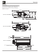
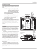
Dimensions Dimensions The following dimensions can assist in determining the best location for your MDLP2. There is additional information on the next page pertaining to installing the MDLP2 into cabinets. 20-1/4" 51.44cm 6-1/4" 15.88cm Front View of the MDLP2 6-3/4" 17.15cm 9-1/2" 24.13cm Adjustable Height Front Feet 20-1/4" 51.44cm 6-3/4" 17.15cm Rear View of the MDLP2 2 13" 33.02cm 1-1/8" 3.18cm (See Note 1) 17-11/16" 44.
Installation Installation Overview For the best possible image reproduction by the McIntosh MDLP2 Video Projector, it is important to observe the following: CAUTION: The MDLP2 Video Projector weight is 40 pounds (18.14 kilograms). When mounting the projector to a building structure it is important to follow all of the local building/constuction codes. 1. Decide on a viewing area with either subdued and/ or controlled ambient lighting. 2.
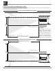
Projector and 16:9 Screen Mounting Location The illustrations below together with the charts on the adjacent page, will help to assure the correct mounting locations for both the projector and the screen. Projector mounted from the ceiling Ceiling Top of Screen Acceptable Projector Mounting Height Vertical Screen Height Vertical Center of Screen Bottom of Screen Distance (Minimum-Maximum) between the Screen and the Projector Lens CAUTION: The MDLP2 Video Projector weight is 40 pounds (18.
Installation, con’t MDLP2M (with Medium Throw Lens) - 16:9 Screen Size (1.77:1 Aspect Ratio) Screen Diagonal Screen Width Screen Height Minimum Distance Maximum Distance Inches 70 72 80 82 84 90 92 100 106 110 120 123 133 135 150 170 200 250 Centimeters Inches 177.8 61 182.9 62-12/16 203.2 69-12/16 208.3 71-8/16 213.4 73-3/16 228.6 78-7/16 233.7 80-3/16 254.0 87-3/16 269.2 92-6/16 279.4 95-14/16 304.8 104-9/16 312.42 107-3/16 337.8 115-15/16 342.9 117-11/16 381.0 130-12/16 431.8 148-3/16 508.
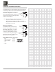
Projector and 4:3 Screen Mounting Location The illustrations below together with the charts on the adjacent page, will help to assure the correct mounting locations for both the projector and the screen. Projector mounted from the ceiling Ceiling Top of Screen Acceptable Projector Mounting Height Vertical Screen Height Vertical Center of Screen Bottom of Screen Distance (Minimum-Maximum) between the Screen and the Projector Lens CAUTION: The MDLP2 Video Projector weight is 40 pounds (18.14 kilograms).
Installation, con’t MDLP2M (with Medium Throw Lens) - 4:3 Screen Size (1.33:1 Aspect Ratio) Screen Diagonal Screen Width Screen Height Minimum Distance Maximum Distance Inches 70 72 80 82 84 90 92 100 106 110 120 123 133 135 150 170 200 250 Centimeters 177.8 182.9 203.2 208.3 213.4 228.6 233.7 254.0 269.2 279.4 304.8 312.42 337.8 342.9 381.0 431.8 508.0 635.0 Inches 56 57-10/16 64 65-10/16 67-3/16 72 73-10/16 80 84-13/16 88 96 98-6-16 106-6/16 108 120 136 160 200 Centimeters 142.2 146.3 162.6 166.6 170.
Initial Setup The Initial Setup Section is to assist with minimizing the possible geometric distortions in the projected image caused by the physical orientation of the MDLP2 Video Projector relative to the screen. While there are electronic adjustments to correct for some of these geometric distortions, the best images will be achieved when minimal electronic adjustments are used.
Initial Setup Screen Figure 8 Screen Figure 9 centered vertically on the screen the Crosshatch Test Pattern lines are again white in color. 9. Using the Knurled Ring surfaces on the projector lens, adjust the size and focus of the image. Refer to figure 7. 10. Rotate one or both of the projector feet to line up the top and bottom horizontal lines of the Crosshatch Test Pattern to be parallel with the top and bottom edges of the screen. Refer to figures 5 and 10.
Rear Panel Connections and Switch DATA IN Port receives signals from McIntosh A/V Control Center for Remote Control Operation COMPONENT INPUTS receive Component Video (Y, PR and PB) Signals from Component Video Sources TRIGGER 1 Output sends a Turn-On signal to other components when the MDLP2 is switched On POWER CONTROL IN receives turn-on signals from a McIntosh component and POWER CONTROL OUT sends turn-on signals on to another McIntosh Component TRIGGER 2 Output sends Turn-On signals to other compo
How to Connect the MDLP2 How to Connect the MDLP2 The MDLP2 has the ability to automatically switch power On/Off to McIntosh Components via the Power Control and Trigger Connections. The Data Port Connections allow for the remote operation of the MDLP2 from other McIntosh Components. With an external sensor connected to the MDLP2, remote control operation is possible when the MDLP2 is located in an enclosure.
Remote Control Push-Buttons LED illuminates during the time a remote command is sent to the MDLP2 Selects which component, either the VP1000 Processor or the MDLP2 Projector, the remote control commands are sent to Used to change the Color Temperature settings Press to adjust the selected function Used to change the Gamma settings Press to recall various On-Screen Information, press a second time to deactivate the Menus Press to change the Aspect Ratio of the video image Press to select one of three prede
How to use the Remote Control How to use the Remote Control The supplied Remote Control is capable of directly controlling the functions of the McIntosh MDLP2 Video Projector and VP1000 Video Processor. For additional information on the various video adjustments and their purpose, please refer to the “How to Operate the MDLP2” section of this manual starting on page 22. Note: At times it might appear the selected function is not responding when using the Remote Control.
Front Panel Push-buttons, Indicators and Control Allows the Projector Lens assembly to be raised or lowered vertically for centering the image on the screen Used to navigate up, down, to the left and to the right through the various menus.
Default Settings Default Settings The Default Settings Charts indicate the On-Screen Menu Name, Function, Default Settings and the page number for additional information. MENU FUNCTION SETTING PAGE Picture Mode Theater Standard (Default) Dynamic User Gamma Contrast Brightness Color Tint Sharpness Color Temp.
How to Operate the MDLP2 Power The Red LED to the left of the STANDBY/ON Push-button lights to indicate the MDLP2 is in Standby mode. To Switch ON the MDLP2, press the STANDBY/ON Pushbutton on the Projector Control Panel or the Projector ON Push-button using the Remote Control. The Green LED to the right of the STANDBY/ON Push-button lights to indicate the MDLP2 is ON. Refer to figures 14 and 15. Notes: 1.
How to Operate the MDLP2 Display Installation Orientation: 1. Press the MENU Push-button on either the Projector Control Panel or on the Remote Control. Refer to figures 14 and 15. 2. Using the Navigation ▲UP or ▼DOWN Push-button, select DISPLAY from the Main Menu choices. Refer to figure 16.
1. Press the MENU Push-button on either the Projector Control Panel or on the Remote Control. Refer to figures 14 and 15. 2. Using the Navigation ▲UP or ▼DOWN Push-button, select CONFIG. from the Main Menu choices. Refer to figure 21.
How to Operate the MDLP2, con’t Fine Menu 1 Adjust In the Fine Menu 1 there are two user type adjustments, image sharpness and noise reduction. The remaining adjustments are best performed by a professional with the necessary video signal generators and optical measurement equipment. Refer to figure 25.
ASPECT RATIO OPTIONS 16:9 VIDEO SOURCE MODE IMAGE INPUT SIGNAL 4:3 VIDEO SOURCE DECRIPTION IMAGE DECRIPTION The Image Source Aspect Ratio is 1.78:1 The Image Source Aspect Ratio is 1.
How to Operate the MDLP2, con’t input signal. The remaining adjustments are for RGB signals and are thus “grayed out”. Standard 1 Picture Adjust 123 Memory 1 Mode Standard 1 Picture Adjust Keystone 0 Fine Menu 1 Scale 0 Fine Menu 2 Width 0 Input Signal Position H 0 RGB/HD Adjust Position V 0 Fine Menu 1 Readjust Fine Menu 2 Resolution H 0 HDMI Color Wheel x5 Input Signal Resolution V 0 Display Installation Front RGB/HD Adjust Position H 0 OSD/Blanking Config.
Status Info. - Displays On-Screen information about the status of the video input signal and when other operational modes are selected. This occurs when the INFO Push-button or other push-buttons are pressed on the Remote Control. Enable: Displays the current status for a set amount of time in the upper righthand corner of the screen. Disable: The information is not displayed.
How to Operate the MDLP2, con’t Wireless: Selects external sensor(s) only. Wired: Selects the two internal sensors and any external sensor(s) connected to the MDLP2. Note: When making a change to the current menu setting, the ENTER Pushbutton on the MDLP2 Control Panel must be used to effect the desired change. Reset Lamp Life - The projection lamp used in the MDLP2 has a maximun life expectancy of 2,000 hours.
Specifications Optical Specifications Digital Micromirror Device 0.95 inch (16:9) 1920 x 1080 pixels Lamp Super High Pressure 200W DC Lens f: 30.7 – 44.5mm (medium throw lens) f: 44.5 – 66.75mm (long throw lens) F: F3.0/F6.0 Projected Image Size 70 to 250 inches (medium throw lens, 1.77:1 aspect ratio) 80 to 300 inches (long throw lens, 1.77:1 aspect ratio) 70 to 250 inches (medium throw lens, 1.33:1 aspect ratio) 60 to 300 inches (long throw lens, 1.
Packing Instructions Packing Instructions In the event it is necessary to repack the equipment for shipment, the equipment must be packed exactly as shown on this page, with the protective cover installed on the projector lens. Failure to do this will result in shipping damage. Use the original shipping carton and interior parts only if they are all in good serviceable condition.
McIntosh Laboratory, Inc. 2 Chambers Street Binghamton, NY 13903 www.mcintoshlabs.com The continuous improvement of its products is the policy of McIntosh Laboratory Incorporated who reserve the right to improve design without notice. Printed in the U.S.A. McIntosh Part No.