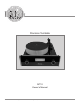
Precision Turntable MT10 Owner’s Manual McIntosh Laboratory, Inc.
The lightning flash with arrowhead, within an equilateral triangle, is intended to alert the user to the presence of uninsulated “dangerous voltage” within the product’s enclosure that may be of sufficient magnitude to constitute a risk of electric shock to persons. WARNING - TO REDUCE RISK OF FIRE OR ELECTRICAL SHOCK, DO NOT EXPOSE THIS EQUIPMENT TO RAIN OR MOISTURE.
Thank You Table of Contents Your decision to own this McIntosh MT10 Precision Turntable and MCC10 Moving Coil Cartridge ranks you at the very top among discriminating music listeners. You now have “The Best.” The McIntosh dedication to “Quality,” is assurance that you will receive many years of musical enjoyment from this unit. Please take a short time to read the information in this manual. We want you to be as familiar as possible with all the features and functions of your new McIntosh.
General Information and Cable Information General Information Connector and Cable Information Caution: To prevent possible damage to the turntable platter bearing, do not move the MT10 Precision Turntable with the platter installed. Power Control Connector The MT10 Power Control Input/Output Jacks receive/send Power On/Off Signals when connected to other McIntosh Components. A 1/8 inch stereo mini phone plug is used for connection to Power the Power Control Input/Output on the Control N/C MT10. 1.
Introduction and Performance Features Introduction The McIntosh MT10 Precision Turntable with the McIntosh MCC10 Moving Coil Cartridge offers the latest in playback of vinyl recordings. A full complement of performance features allows for the enjoyment of all recordings reproduced with flawless realism. The advanced electronic and mechanical design ensures many years of smooth trouble free operation.
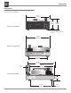
Dimensions Dimensions The following dimensions can assist in determining the best location for your MT10. 17-1/2" 44.45cm 8-3/16" 20.80cm 8-13/16" 22.38cm Front View of the MT10 Note: The above height measurments are with the McIntosh Cartridge installed. 16-5/8" 42.23cm Rear View of the MT10 13-13/16" 32.54cm 17-3/4" 45.10cm 1" 2.54cm 16-1/4" 41.28cm Side View of the MT10 3-7/8" 9.84cm 13-13/16" 32.54cm 6 1-5/8" 4.
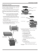
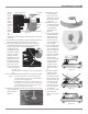
Unpacking the Turntable Unpacking the Turntable To protect the fine finish of the MT10 Precision Turntable during the assembly and adjustment process, it is advisable to prepare a suitable clean working area with a soft, clean fabric, such as a bed linen or blanket. It is recommended that the Professionals at your McIntosh Dealer, who are skilled in all aspects of installation and operation, unpack, assemble, adjust and install the MT10 Precision Turntable and any associated audio equipment.
Assembling the Turntable Locate the McIntosh MCC10 Moving Coil Cartridge, Tools and Mounting Hardware from the Accessory Box. In the following steps the Cartridge will be installed in the Tone Arm Headshell of the Turntable. Cartridge Mounting Screws Tone Arm Headshell CAUTION: To prevent possible damage to the Cartridge Stylus, DO NOT remove the clear protective cover at this time. 1.
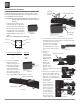
Assembling the Turntable up with Rear of Tone Arm knurled the Mcknob Intosh MCC10 Cartridge postion Counter marking Weight on the suface. Refer to McIntosh MCC10 Position Marking figure Figure 13 13. Then tighten the knurled knob to secure the position of the Counter Weight. 9. Locate the Tone Arm Height Gauge (used for the McIntosh MCC10 Cartridge) from inside the accessory box. 10. The gauge should just fit between the Tone Arm Housing and the Mounting Plate of the Tone Arm.
Assembling the Turntable, con’t 19. Locate the McIntosh Bubble Level and place it on the Turntable Platter Mat. If the Bubble is not in the center circle Figure 21 of the Bubble Level adjust the height the Turntable Feet (by rotating them clockwise or counter clockwise) until it is level. Refer to figure 21. 20. Carefully slide off the clear protective cover from the cartridge by pulling the cover straight toward you. 21. Proceed to Rear Panel Connections.
Rear Panel Connections and Adjustments AUDIO OUTPUTS connect to MC (Moving Coil) Inputs of the Preamplifier or A/V Control Center when the McIntosh MCC10 Cartridge is installed. Contact your McIntosh Dealer for additional assistance. POWER CONTROL REMOTE IN receives turn-on signals from a McIntosh component and switches the Front Panel Illumination On/Off.
How to Connect the Turntable How to Connect the Turntable 1. Connect a Power Control Cable from the MT10 POWER CONTROL REMOTE IN to the POWER CONTROL ACC Output jack of a McIntosh Preamplifier or A/V Control Center. 2. Optionally, connect a Power Control Cable from the MT10 POWER CONTROL REMOTE OUT to the POWER CONTROL IN jack of a McIntosh source component. 3. Connect a wire from the MT10 GND (Ground) Post to the GND (Ground) post on the McIntosh Preamplifier or A/V Control Center. 4.
Front Panel Display, Switches, Lever and Record Clamp Raises and lowers the Tuntable Tone Arm Record clamp helps to keep the phonograph recording flat during playback SPEED Switch selects one of three playback speeds, 331/3 rpm, 45 rpm or 78 rpm POWER Switch turns AC Power On/Off, or Standby for Illumination only Meter indicates actual rotation speed of the turntable platter 13
How to Operate the Turntable How to Operate the Turntable Power Selection Rotate the POWER Switch to select the Turntable operation mode you desire. Refer to figure 50. Power Off - The Front Panel and Turntable Platter lights are turned Off. There is no Turntable Platter rotation. Standby - The Front Panel and TurnFigure 50 table Platter will illuminate when the McIntosh Preamplifer or A/V Control Center is turned On. There is no Turntable Platter rotation.
Notes 15
Notes 17
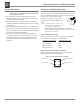
MCC10 Cartridge Specifications MT10 External Power Supply Specifications Output Level 0.5 mV at 5 cm/s Output Voltage 24 Volts, 625ma Load Impedance Greater than 200 ohms, 500 ohms recommended Power Requirement 100 Volts, 50/60Hz at 400ma 110 Volts, 50/60Hz at 400ma 120 Volts, 50/60Hz at 400ma 220 Volts, 50/60Hz at 400ma 230 Volts, 50/60Hz at 400ma 240 Volts, 50/60Hz at 400ma Frequency Response 20Hz to 50,000Hz Compliance 6 x 10⁻⁶ cm/dyne Recommended Tracking Force 2.4 g Channel Difference Less than 0.
Packing Instructions Packing Instructions In the event it is necessary to repack the equipment for shipment, the equipment must be packed exactly as shown below. It is very important the four feet are still attached to the bottom of the equipment. This will ensure the proper equipment location on the bottom pad. Failure to do this will result in shipping damage. Use the original shipping carton and interior parts only if they are all in good serviceable condition.
McIntosh Laboratory, Inc. 2 Chambers Street Binghamton, NY 13903 The continuous improvement of its products is the policy of McIntosh Laboratory Incorporated who reserve the right to improve design without notice. Printed in the U.S.A. McIntosh Part No.