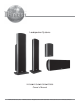
Loudspeaker Systems XLS360yXLS340yXLS320yXCS350 Owner’s Manual McIntosh Laboratory, Inc.
WARNING - TO REDUCE RISK OF FIRE OR ELECTRICAL SHOCK, DO NOT EXPOSE THIS EQUIPMENT TO RAIN OR MOISTURE. NO USER-SERVICEABLE PARTS INSIDE. REFER SERVICING TO QUALIFIED PERSONNEL. To prevent the risk of electric shock, do not remove cover or back. No user serviceable parts inside. IMPORTANT SAFETY INSTRUCTIONS! PLEASE READ THEM BEFORE OPERATING THIS EQUIPMENT. 1. Read these instructions. 2. Keep these instructions. 3. Heed all warnings. 4. Follow all instructions. 5. Do not use this apparatus near water. 6.
Thank You Table of Contents Your decision to own a McIntosh Loudspeaker System ranks you at the very top among discriminating music listeners. You now have “The Best.” The McIntosh dedication to “Quality,” is assurance that you will receive many years of musical enjoyment from this unit. Please take a short time to read the information in this manual. We want you to be as familiar as possible with all the features and functions of your new McIntosh. Safety Instructions ...................................
Important Information Introduction Caution: The XLS360 Loudspeaker weight is 107 pounds (48.5kg) net. It requires two or more persons to handle safely. 1. Loudspeaker Cables of adequate size are important to ensure that there will be no significant power loss or heating. Cable size is specified in Gauge numbers or AWG (American Wire Gauge).
Important Information, Connector Information, Introduction and Performance Features Performance Features • Patented LD/HP Technology • High Power Handling The McIntosh Low Frequency and Midrange Loudspeaker Elements feature the patented LD/HP motor structure. This design, when compared to conventional Loudspeaker Elements, reduces distortion significantly. It also increases power handling and efficiency.
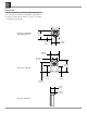
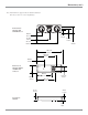
Dimensions The following dimensions can assist in determining the best location for the XLS320 or XLS340 Loudspeaker System. There is additional information on page 18 pertaining to installing the Loudspeaker. Front View of XLS320 with Grille Removed 10-5/8" 27.0cm 5-13/16" 14.8cm 5-5/16" 13.5cm 10-5/8" 27.0cm 6-11/16" 17.0cm 15-5/16" 38.9cm Rear View of XLS320 8-9/16" 21.7cm 7-5/16" 18.6cm 12-5/8" 32.0cm 5-1/4" 13.3cm 4-1/2" 11.
Dimensions Front View of XLS340 with Grille Removed Rear View of XLS340 10-5/8" 27.0cm 39-3/8" 100.0cm 44-1/16" 111.9cm 4-1/16" 10.3cm 34-9/16" 35-9/32" 87.8cm 89.6cm 24-11/16" 62.7cm 15-3/16" 38.6cm 18" 2-1/16" 4-1/16" 10.3cm 45.7cm 5.2cm 5-13/16" 5.8cm 14-3/4" 5-1/4" 13.3cm 37.5cm 4-1/2" 11.4cm 7-3/8" 18.7cm Note: The XLS340 is supplied with optional adjustable feet, four Tiptoes and four Glides. If they are used with the XLS340 please allow for the added height.
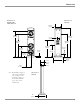
Dimensions, con’t The following dimensions can assist in determining the best location for the XLS360 or XCS350 Loudspeaker System. There is additional information on page 18 pertaining to installing the Loudspeaker. 13-1/8" 33.3cm Front View of XLS360 with Grille Removed Rear View of XLS360 4-1/16" 10.3cm 46-9/16" 118.3cm 51-3/8" 130.5cm 41-3/4" 106.0cm 37-3/4" 95.9cm 33-15/16" 86.2cm 19-3/16" 48.7cm 2-1/16" 27-1/4" 69.2cm 5.2cm 7-3/16" 18.3cm 17-3/4" 8-7/8" 22.5cm 45.1cm 9-1/4" 23.
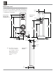
Dimensions, con’t Note: The XCS350 is supplied with an adjustable Stabilizer Bar. Please allow for various height/angle. Front View of XCS350 with Grille Removed 6-9/16" 16.7cm 4-3/16" 10.6cm 17-1/32" 5-5/16" 13.5cm 43.3cm 27-1/2" 9" 69.9cm 22.9cm 34-1/16" 86.5cm 25-9/16" 64.9cm 9-9/16" 24.3cm Rear View of XCS350 with the stabilizer bar removed 20-1/8" 51.1cm 10-5/8" 27.0cm 6-11/16" 17.0cm 24-3/16" 61.4cm 5-1/4" 13.3cm 4-1/2" 11.4cm Top View of XCS350 3/4" 1.
Installation Installation Overview The instructions that follow are for the unpacking, assembly and setup of the XLS320, XLS340, XLS360 and XCS350 Loudspeaker Systems as supplied. For several models, an optional In Wall Mounting Kit is available. If the Loudspeaker is to be Mounted On or In Wall, refer to “Locating the Loudspeaker System” on page 18, “Tweeter Array Optimization” on page 19 and “How to Connect” starting on page 20, before beginning the Mounting Process.
Installation 6. Place the Loudspeaker System, with the front facing up, on foam end caps located on top of the shipping carton, with the bottom of the XLS340 overhanging the end of the shipping carton. Refer to figure 3. Bottom of XLS340 with the flat surface 11. Orient the Loudspeaker and the Grille with the rounded ends pointing in the same direction. 12. Align the Grille fasteners to the Loudspeaker Grommets (three on each side). Carefully push down to secure the Grille to the Loudspeaker.
Installation, con’t Bottom of XLS360 with the flat surface Foam center cap Foam end cap independently adjusted to compensate for uneven flooring. 12. Proceed to “Locating the Loudspeaker System” on page 18. Figure 6 8. Orient the Floor Standing Base with the widest end of the base facing up and the totally flat side of the base pointing away from the XLS360. Refer to figure 7. Grommets Fasteners Notes: 1. When the XCS350 is to be used with the supplied Stabilizer Bar and Hardware, proceed to step 6.
Installation, con’t 7. Attach the four rubber bumpers to the bottom long edge of the XCS350 Loudspeaker System. Refer to figure 8. 8. Loosen, but do not remove, the three screws securing the Stabilizer Bar to the back of the XCS350. Refer to figure 9. Grommets Fasteners Grille Stabilizer Bar Screws Stabilizer Bar Figure 9 9. Reposition the Stabilizer Bar even with the previously applied rubber bumpers on the side edge of the XCS350 enclosure. Refer to figure 10. Figure 10 10.
Installation, con’t 2. Attach either the flush mount or angle mount bracket to the rear of the Loudspeaker using the two screws (just removed in the previous step), being sure to orient the bracket as illustrated in figures 15 and 16. 3. Determine the Loudspeaker Mounting Location on the wall, making sure the Mounting Bracket will be anchored to a stud located inside the wall. two cone shaped rubber bumpers to the rear of the Loudspeaker, near the bottom.
Installation, con’t Note: Use extreme caution to avoid any existing electrical wiring, plumbing, etc., located inside the wall. 4. Refer to figures 23 and 24 to install the appropriate Wall Brackets on the wall (orient the bracket as illustrated) using the supplied Mounting Screws. If the Flush Mount Brackets are used, optionally attach the two cone shaped rubber bumpers to the rear of the Loudspeaker, near the bottom.
Installation, con’t How to Mount the XCS350 Loudspeaker On the Wall The supplied On Wall Mounting Brackets allow for four different mounting positions of the XCS350 Loudspeaker relative to the wall, both vertical and horizontial. Two positions are flush mount, with the Loudspeaker close to and parallel with the wall. The other positions are angle mount, which places the Loudspeaker further away from the wall and allows for rotation of ± 30 Degrees. Refer to figure 25.
Installation, con’t 6. Align the Grille fasteners to the Loudspeaker Grommets (four on each side). Carefully push down to secure the Grille to the Loudspeaker.
Installation, con’t Locating the Loudspeaker System Loudspeaker placement in a room can greatly affect performance. The XLS320, XLS340, XLS360 and XCS350 are designed for use as a Left and Right Loudspeaker in a Music System, or as a Front and Surround Loudspeakers in a Home Theater System. The optimal method for selecting speaker locations includes the use of a real time spectrum analyzer operated by the Professionals at your McIntosh Dealer.
Installation, con’t Tweeter Array Optimization The XLS320, XLS340, XLS360 and XCS350 Loudspeaker Systems incorporate a special feature in the Crossover Network for optimization of the sound coming from the five tweeter array, refer to figure 37. The three different settings in the crossover network have to do with the physical location of the Loudspeaker in Figure 37 the Home Theater and/or Music System.
Connection for use with a Low Power Amplifier (default setting) Preparing Hookup Cables The McIntosh Loudspeaker Systems utilize binding posts for speaker wire connections. Prepare the Loudspeaker Hookup Cables that attach to the Power Amplifier Output Terminals: Bare wire cable ends: Carefully remove sufficient insulation from the cable ends, refer to figures 43, 44 and 45. If the cable is stranded, carefully twist the strands together as tightly as possible. 3.
How to Connect the XLS320 Loudspeakers Connection for use with a High Power Amplifier (optional setting) Preparing Hookup Cables The McIntosh Loudspeaker Systems utilize binding posts for speaker wire connections. Prepare the Loudspeaker Hookup Cables that attach to the Power Amplifier Output Terminals: Bare wire cable ends: Carefully remove sufficient insulation from the cable ends, refer to figures 43, 44 and 45. If the cable is stranded, carefully twist the strands together as tightly as possible. 3.
Connection with one Amplifier Preparing Hookup Cables The McIntosh Loudspeaker Systems utilize binding posts for speaker wire connections. Prepare the Loudspeaker Hookup Cables that attach to the Power Amplifier Output Terminals: Bare wire cable ends: Carefully remove sufficient insulation from the cable ends, refer to figures 43, 44 and 45. If the cable is stranded, carefully twist the strands together as tightly as possible. 3. Tighten all of the Loudspeaker and Amplifier Binding Posts. 4.
How to Connect the XLS340, XLS360 and XCS350 Loudspeakers Connection with two Amplifiers Preparing Hookup Cables The McIntosh Loudspeaker Systems utilize binding posts for speaker wire connections. Prepare the Loudspeaker Hookup Cables that attach to the Power Amplifier Output Terminals: Bare wire cable ends: Carefully remove sufficient insulation from the cable ends, refer to figures 43, 44 and 45. If the cable is stranded, carefully twist the strands together as tightly as possible.
XLS320 Specifications XLS340 Specifications Driver Complement One 6-1/2 inch LD/HP Woofers/Midrange Five 1 inch Dome Tweeters (in a Bessel Function Array) Driver Complement Two 8 inch LD/HP Woofers One 6-1/2 inch LD/HP Midrange Five 1 inch Dome Tweeters (in a Bessel Function Array) Impedance 8 ohms Nominal Frequency Response 50Hz - 34kHz -6dB (Typical Room) 80Hz - 34kHz + 2dB (Anechoic Response) High Pass Filter (High Power Connection) 12dB per octave roll off below 80Hz Sensitivity 85dB (2.
Specifications XLS360 Specifications XCS350 Specifications Driver Complement Two 10 inch LD/HP Woofers One 6-1/2 inch LD/HP Midrange Five 1 inch Dome Tweeters (in a Bessel Function Array) Driver Complement Two 8 inch LD/HP Woofers One 6-1/2 inch LD/HP Midrange Five 1 inch Dome Tweeters (in a Bessel Function Array) Impedance 8 ohms Nominal Impedance 8 ohms Nominal Frequency Response 34Hz - 34kHz -6dB (Typical Room) 55Hz - 34kHz + 2dB (Anechoic Response) Frequency Response 45Hz - 34kHz -6dB (Typical Ro
Packing Instructions In the event it is necessary to repack the equipment for shipment, the equipment must be packed exactly as shown below. The XLS360 shipping carton uses banding straps to make sure the box is held together securely. Note: The Floor Stand must be removed from the XLS340/ XLS360 Loudspeaker and packed in its own shipping carton. Use the original shipping carton and parts only if they are in good serviceable condition.
Packing Instructions XLS360 Shipping Cartons and Parts List Quantity 1 1 2 1 1 1 Part Number 034290 034289 034244 034245 034309 033300 1 033085 Description Shipping carton top Shipping carton bottom Foam end caps Foam center cap Floor stand shipping carton Microfoam to wrap up the floor stand Air Cap bottom pad XCS350 Shipping Carton and Parts List 27
McIntosh Laboratory, Inc. 2 Chambers Street Binghamton, NY 13903 The continuous improvement of its products is the policy of McIntosh Laboratory Incorporated who reserve the right to improve design without notice. Printed in the U.S.A. McIntosh Part No.