INSTRUCTION MANUAL T-Series™ Air Conditioner T43 Model Protecting Electronics. Exceeding Expectations.™ MAI 5736 North Michigan Road Indianapolis, IN 46228 McLean Cooling Technology 11611 Business Park Blvd N Champlin, MN 55316 USA 317-257-6811 Tel 763-323-8200 317-257-1590 fax Fax 763-576-3200 www.McLeanParts.net 10-1008-14 1455-Re Rev. v.
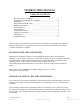
INSTRUCTION MANUAL TABLE OF CONTENTS Receiving the Air Conditioner ...............................................................1 Handling and Testing the Air Conditioner.............................................1 Installation..............................................................................................2 Design Data, Model Drawing ................................................................3 Mounting Instructions.......................................................................
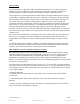
TEST FOR FUNCTIONALITY BEFORE MOUNTING THE AIR CONDITIONER TO THE ENCLOSURE. Refer to nameplate for proper electrical current requirements, then connect power cord to a properly grounded power supply. Minimum circuit ampacity should be at least 125% of the amperage shown in the design data section for the appropriate model. No other equipment should be connected to this circuit to prevent overloading. Operate the air conditioner for five (5) to ten (10) minutes.
T43 Series 6000-10000 Btuh (1756-2928 Watts) H x W x D: 43" (1092) x 15.75" (400) x 11" (279) Full BTU/Hr @ Max Amb Shipping Load Max Amb Temp Weight o o F/ C Lbs/Kgs Model Voltage Hz Amps Phase Temp T43-0616-G15X 115 50/60 8.6 1 6310/6680 131/55 125/57 T43-0626-G15X 230 50/60 3.8 1 6520/6770 131/55 125/57 T43-0816-G15X 115 50/60 10.4/11.2 1 7900/8600 131/55 125/57 T43-0826-G15X 230 50/60 5.2/5.4 1 7400/8200 131/55 125/57 T43-1016-G15X 115 50/60 16/20 1 9670/10290 131/55 125/57 T43-1026-G15X 230 50/60 9.
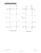
T43 Mounting Cutout Dimensions External Cutout Internal Cutout 10-1008-145 Rev. 10 317-257-6811 Page 4 www.McLeanParts.
T43 Mounting Gasket Kit 10-1008-145 Rev. 10 317-257-6811 Page 5 www.McLeanParts.
T43 Series Components List Part Number (115 Volt) Part Description Capacitor, Compressor, Start Capacitor, Compressor, Run 6000 BTU 8000 BTU 10000 BTU 10-1032-05 10-1032-08 10-1032-32 S-6173 52-6032-01 52-6032-06 Capacitor, Impeller, Condenser 52-6084-01 52-6084-01 52-6031-03 Capacitor, Impeller, Evaporator 52-6084-01 52-6084-01 52-6084-01 Coil, Condenser 45-6051-00 45-6051-00 45-6051-00 Coil, Evaporator 43-6025-00 45-6050-00 45-6050-00 Compressor, RKA 10-1016-86 10-1016-85 10-1
T43 Generic Schematic (actual unit options may vary) T43 Generic Wire Diagram (actual unit options may vary) 10-1008-145 Rev. 10 317-257-6811 Page 7 www.McLeanParts.
TEMPERATURE CONTROL The electromechanical thermostat is factory preset to 75oF/24oC. To change the temperature setting, remove the nylon plug (if applicable) from the back face of the unit. Use a standard screwdriver to adjust thermostat. For cooler temperatures turn clockwise, for warmer temperatures turn counterclockwise. The set point of the thermostat equals the off temperature. The on temperature is 10°F/5oC above the set point. UNITS WITH HEAT The heating thermostat is factory preset to 55°F/13oC.
Inlet Air Filter Proper maintenance of the inlet air filter, located behind the front cover, will assure normal operation of the air conditioner. If filter maintenance is delayed or ignored, the maximum ambient temperatures under which the unit is designed to operate will be decreased.
Condenser and Evaporator Air Movers Impeller motors require no maintenance. All bearings, shafts, etc. are lubricated during manufacturing for the life of the motor. If the condenser impeller motor (ambient impeller) should fail, it is not necessary to remove the air conditioner from the cabinet or enclosure to replace the blower. The condenser blower is mounted on its own bulkhead and is easily accessible by removing the lower access panel.
TROUBLE SHOOTING Basic Air Conditioning Trouble Shooting Check List 1. Check manufacturer’s nameplate located on the unit for correct power supply. 2. Turn the power to the unit on. The evaporator (Enclosure or “COLD” air) impeller should come on. Is there airflow? YES, proceed to step # 3. NO, possible: 3. Repair or Replace defective part Open motor winding Stuck impeller motor Obstructed wheel Check thermostat setting? Adjust thermostat to the lowest setting.
Symptoms and Possible Causes: SYMPTOM POSSIBLE CAUSE Unit won’t cool * Clogged fins on coil(s) * Dirty filter * Impellers not running * Compressor not running * Compressor runs, but has bad valves * Loss of refrigerant Compressor tries to start but won’t run * Low line voltage at start.
MAI 5736 North Michigan Road ©2008 McLean Midwest Corporation Indianapolis, IN 46228 317-257-6811 McLean Cooling Technology 317-257-1590 11611 Business Parkfax Blvd N Champlin, MN 55316 USA Tel 763-323-8200 Fax 763-576-3200 www.McLeanParts.net Protecting Electronics. Exceeding Expectations.